Advertisement
Quick Links
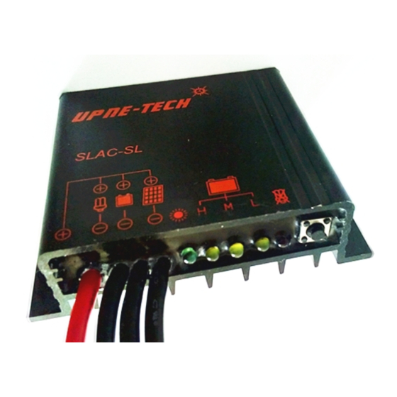
SLAC-SL Solar street light controller
Thank you very much for choosing our product.
This product manual provides important information and advices for
product installation, use and troubleshooting. Before using this product,
please read carefully and thoroughly.
SLAC-SL is specially designed for solar street light with high
performance. It has a number of outstanding features:
The controller adjusts itself automatically to 12V or 24V system voltage.
Sophisticated programmable nightlight function.
Clear readable LED display of the state of charge.
4 stage charging(Main,boost, equalization, float) for flooded battery, 3
stage charging(boost, float) for sealed battery.
Enclosed by aluminum shell and potted by epoxy with high thermal
conductivity. Protection grade reaches IP67.
Safety recommendations
Recommend a wire diameter: SLAC - SL10A: 1.5 mm²; SLAC -
SL20A: 2.5 mm ²,ensure the battery and the controller between the
cable length as short as possible, to prevent controller misjudge battery
voltage.
Connect the controller by following steps to avoid installation faults.
1. Connect the wire to the controller, then to the battery.
2. Connect the wire to the controller, then to the photovoltaic modules.
3. Connect the wire to the load, then to the controller.
(3)
(1)
Starting up the controller:
Self Test
As soon as the controller is supplied with power either from the battery or
the solar array, it starts a self test routine. Then the display changes to
normal operation.
System Voltage
The controller adjusts itself automatically to 12V or 24 V system
voltages. As soon as the voltage at the time of start-up exceeds 20.0V,
the controller assumes a 24V system. If the battery voltage is not
within the normal operation range at start-up, a status display according
to the section ERROR DESCRIPTION occurs.
LED Status and Display
SLAC-SL Controller has five LEDs. One green LED is for charge
display, three yellow LEDs are for the state of charge display, and one
red LED is for the status of load display.
Normal operation Description
LED
Status
On
Slow flash
Green
Fast flash
LED
Off
Yellow LED 1(L) on
Yellow
LED
Yellow LED 2(M) on
User Manual
(2)
Function
Main charge during daytime
Float charge
Equalization charge
Controller connected to battery, night
detected.
Battery power low
Battery power medium
Yellow LED 3(H) on
Off
Red
LED
Flash
Error Description
Indication
Loads are not
supplied.
Battery is low
after short
time.
Battery is not
being charged
during
daytime.
Nightlight Function
The controller comes with a sophisticated nightlight function. It controls
the load output at night and is widely programmable. Two modes are
available: Dusk to Dawn and Evening timing.
Dust to Dawn
Light on
Light on
Hours after dusk
The mode can be selected in Programming Main Menu 1. If Evening
timing mode is selected. Programming Menu 2 allows choosing the
Evening timing hours.
The controller recognizes day and night based on the solar array open
circuit voltage (Factory setting is 5.0V for 12V system, 10.0V for 24V
system). In Programming Main Menu 3 this day/night threshold can be
modified according to the requirements of the local conditions and the
solar array used.
To find the right value, we recommend measuring the solar array open
circuit voltage at the time when twilight has reached the level when the
controller should switch on/off. This value can then be set according to the
description in the programming section.
Mind that the load output is switched off as soon as the battery has
reached the Low Voltage Disconnect threshold, the Low Voltage
Disconnect had priority above the nightlight function.
Both state changes require several minutes of continuous transition values
before making the change. These restrictions avoid false transitions due to
dark storm clouds or lightning.
1
Battery power high
Normal operation
Overload or Short-circuit of load
Cause
Corrective action
Load will reconnect as
Battery is low
soon as battery is
(Red LED on)
recharged
Switch off all loads.
Over current /
Remove short circuit.
Short circuit of
Controller will switch on
loads(Red LED
load automatically after
flashing)
max 1 minute.
Battery voltage
Check if other sources
too high
overcharge the battery. If
(>15.5 / 31.0 V)
not, controller is damaged
Battery wires or
battery fuse
Check battery wires, fuses
damaged, battery
and battery. Remove
has high
faults.
resistance
Battery has low
capacity(Red
Replace the battery.
LED on)
Solar array faulty
or wrong polarity
Check solar array and
(Green LED
wiring. Remove faults.
off)
Evening timing
Light off
Light off
Advertisement

Related Manuals for Upne-Tech SLAC-SL


Summary of Contents for Upne-Tech SLAC-SL
- Page 1 LED Status and Display Evening timing hours. SLAC-SL Controller has five LEDs. One green LED is for charge The controller recognizes day and night based on the solar array open display, three yellow LEDs are for the state of charge display, and one circuit voltage (Factory setting is 5.0V for 12V system, 10.0V for 24V...
- Page 2 Under voltage protection 10.8/21.6V Testing Function Overvoltage protection 15.5/31.0 V During the daytime the testing function of SLAC-SL can help the user to 4mA-5mA(12V) Self consumption verify correct installation or for troubleshooting a system problem. Short 6mA-8mA(24V) pushing the button will light up the lamp which is connected to the load Max.
- Page 3 SLAC-SL Solar Street Light Controller Programming Manual Normal Operation LED Flash LED Fast LED Slow LED off LED on Green Flash Red LED Flash Yellow LED2 Button Yellow Yellow LED1 LED3 Long Push > 2 Second Short Push < 1 Second...