Advertisement
Quick Links
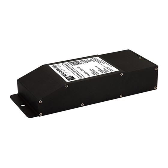
E-SERIES LISTED
FOR MODELS
E20L24DC, E40L24DC, E60L24DC, E75L24DC, E96L24DC
General
This driver is to be installed in accordance with Article 450 of the
National Electric Code. The driver must be installed in a well-ventilated
area free from explosive gases and vapors. Proper operation requires
for free flow of air. This driver should only be installed by a qualified
electrician.
Precautions Before Installing
Check the label and ensure the driver has the proper input voltage and
wattage for the job. Check the wire markings to ensure they match the
wiring diagram on this installation guide.
Mounting
Select a suitable location capable of supporting the weight of the
driver. Use the two key holes in the wire housing and third hold on the
flange when mounting. It is recommended that the driver be mounted
vertically with the wiring compartment pointing down. Recommended
spacing between drivers is 5".
Mounting
Holes
5" Min.
Spacing
Wiring
Compartment
Input Connections / Grounding
1
Remove wire compartment cover plate.
Magnitude, Inc.
14711 Bentley Circle. Tustin, CA 92780
Quick Specs
Input Voltage
Output Voltage
Max. Ambient Temp.
Enclosure
Min. Installation Space
Between Drivers
Remove knockouts and install wire strain reliefs.
www.MagnitudeInc.com
INSTALLATION GUIDE
E-SERIES
120VAC / 24VDC
120V AC
24V DC
-200 C to 700 C (-4°F - 158°F)
Nema 3R - Outdoor Use
5" Inch
technical@MagnitudeInc.com
Page 1 of 2
DOC-GU-400048 Rev. 1
Advertisement

Related Manuals for MAGNITUDE LIGHTING E Series

Summary of Contents for MAGNITUDE LIGHTING E Series
- Page 1 INSTALLATION GUIDE E-SERIES 120VAC / 24VDC E-SERIES LISTED FOR MODELS E20L24DC, E40L24DC, E60L24DC, E75L24DC, E96L24DC General Quick Specs This driver is to be installed in accordance with Article 450 of the Input Voltage 120V AC National Electric Code. The driver must be installed in a well-ventilated Output Voltage 24V DC area free from explosive gases and vapors.
- Page 2 INSTALLATION GUIDE E-SERIES 120VAC / 24VDC With power turned off, route the input wires through a strain relief and connect one wire to black and one wire to white. for all wire connections use only UL listed wire nuts and connectors of suitable size and type.