Advertisement
Quick Links
Battery backup enable/disable
(Link PLK2) Available on NC942B controllers only
Link PLK2 enables or disables the call controller's 500mAHr rechargeable battery
backup facility. Note that this facility is available on NC942B call controllers only.
When enabled (link PLK2 fitted), the NC942B's onboard battery backup supply
will continue to power the system for approximately 24 hours (standby) plus 15
minutes (alarm running time) in the event of a mains failure. This will be indicated by the
controller's 'ON' LED flashing green approximately once per second.
Should the mains supply remain disconnected for a prolonged period of time, the battery
backup facility will automatically shutdown to prevent the batteries from deep discharge.
The default setting for Link PLK2 is link not fitted/battery disabled. This is to conserve bat-
tery life and ensure the safety of the controller during storage/transit. Note that the shorting
link required to enable the facility is provided in the controller's accessory pack.
Sounder and LED test facility
Pressing the controller's RESET button when link PLK1 is fitted in the Reset (a) position will
make its sounder and alarm LED activate. When released, the LED and sounder will switch off.
BASIC OPERATION
The green power 'ON' indicator indicates that the call controller is powered up.
When a standard call is triggered at any device connected to the controller (see figure 1), the
controller's sounder will generate a constant tone and its red 'CALLING' LED will illuminate.
The call controller's relay will also activate and any external equipment connected to the
controller's relay contacts (see page 3) will operate as configured.
Depending on how Link PLK1 has been configured (see page 3), pressing the controller's
'RESET' button will (a) reset the call (b) mute the call or (c) have no effect. (Note that standard
calls can also be cancelled at the device that originated the call if it has a reset facility or via
a remote reset point).
If an emergency call is triggered on a device connected to the controller, the call controller's
sounder will pulse and its red 'CALLING' LED will flash. The controller's relay will also pulse
and any external equipment connected to the controller's relay contacts (see page 3) will
operate as configured. Note that emergency calls override standard calls and can only be
reset at the device from which they were generated.
TECHNICAL SPECIFICATION
Mains supply:
Voltage: 230V a.c.; Max current: 23mA; Frequency: 50Hz.
Output:
Voltage: 12V d.c.; Current: 140mA;
Volt-free relay contacts (NO/C/NC) rated at 30V d.c. @ 1A
Indicators:
Red alarm present LED; Green supply present LED (flashes green on
NC942B model only when battery back up is active)
Sounder:
Active in alarm.
Controls:
'RESET' Button (link selectable for reset, mute or no function).
IP Rating:
IP31 when correctly installed.
Dimensions:
147 x 87 x 39mm (WxHxD). Mounts on 25mm UK double gang back box.
© 2005. Approved Document No: DNU0942000 Rev 1. We reserve the right to alter product specifications at our
discretion and without prior notice. Errors and omissions excepted. This manual has been carefully checked prior
to publication. However, no responsibility can be accepted by the manufacturer or distributors of this equipment
for any misinterpretation of an instruction or guidance note or for the compliance of the system as a whole.
Fit!to
Enable
battery
PLK2
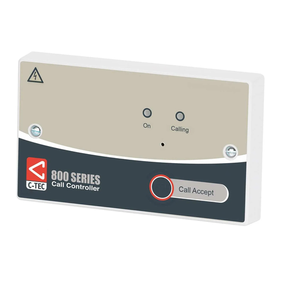
Call Controller
This equipment must be installed and maintained by a suitably skilled
!
and technically competent person.
This Call Controller is a piece of Class 2 equipment. However, any metal parts used during
installation (i.e. metal back box) MUST be earthed. The earth termination point on the One
Zone Call Controller is provided for installer convenience only and, as such, should only be
used if an earth connection is not required elsewhere.
GENERAL
The NC942 is a one zone call controller with a built-in mains to regulated 12V d.c. 140mA
power supply. Its features include a volume adjustable sounder, a link-selectable mute/reset
button, a Power 'ON' LED, an Alarm 'CALLING' LED and a volt-free relay output (for optional
interfacing to externally powered beacons, strobes or other ancillary devices). It also features
a Braille text label for ease of use by the visually impaired.
The NC942B call controller includes all of the above plus an additional on-board rechargeable
battery backup facility providing up to 24 hours standby and 15 minutes alarm running time.
Both controllers are fully compatible with our entire range of 800 Series Call System
components, making them ideal for virtually all single zone applications including disabled
persons toilet alarms.
N C 9 4 2 / N C 9 4 2 B
One Zone
I N S T A L L A T I ON I N S T R U C T I O N S
Approved Document No: DNU0942000 Rev 1 • Page 1 of 4
Advertisement

Related Manuals for C-TEC 800 Series


Summary of Contents for C-TEC 800 Series
- Page 1 24 hours standby and 15 minutes alarm running time. Controls: ‘RESET’ Button (link selectable for reset, mute or no function). Both controllers are fully compatible with our entire range of 800 Series Call System IP Rating: IP31 when correctly installed.
- Page 2 Light c/w Sounder Ceiling Pull Call Controller active will return the controller to its normal state. A maximum of five 800 Series devices (ceiling pulls, call points, overdoor lights, (b) Mute the system T&E Reset!!!!!!!!!!!!!!!Mute reset points, etc.), can typically be connected to the call controller. Always refer In this position, pressing the controller’s RESET button when a standard call is...