Advertisement
Quick Links
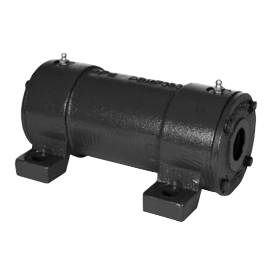
Instruction Manual for Dodge PDNF Mono-Blocks
These instructions must be read thoroughly before installation or operation. This instruction manual was accurate at the time of
printing. Please see dodgeindustrial.com for updated instruction manuals.
WARNING: To ensure the drive is not unexpectedly
started, turn off and lock-out or tag power source before
proceeding. Failure to observe these precautions could
result in bodily injury.
WARNING: All products over 25 kg (55 lbs) are noted on the
shipping package. Proper lifting practices are required for
these products.
WARNING: Because of the possible danger to person(s)
or property from accidents which may result from the
improper use of products, it is important that correct
procedures be followed. Products must be used in
accordance with the engineering information specified
in the catalog. Proper installation, maintenance and
operation procedures must be observed. The instructions
in the instruction manuals must be followed. Inspections
should be made as necessary to assure safe operation
under prevailing conditions. Proper guards and other
suitable safety devices or procedures as may be
desirable or as may be specified in safety codes should
be provided, and are neither provided by Dodge nor are
the responsibility of Dodge. This unit and its associated
equipment must be installed, adjusted and maintained by
qualified personnel who are familiar with the construction
and operation of all equipment in the system and the
potential hazards involved. When risk to persons or
property may be involved, a holding device must be an
integral part of the driven equipment beyond the speed
reducer output shaft.
INSTALLATION:
PDNF mono-blocks, when ordered without the shaft, should
come with one (1) housing, two (2) end covers and associated
bolts, two (2) grease slingers, and two (2) felt seals. Components
ordered separately are: two (2) bearing inserts, usually 300 series
single row deep groove ball bearings, and one (1) wave spring
washer.
When Provided Without the Shaft
Instructions
1.
Install grease slingers onto the shaft with the flange (slinger
portion) mounted against the shaft shoulder (see figure
above). The slinger ring is designed for a clearance fit on
the shaft. If required, use a press or heat the slinger to
approximately 200° F. and slide onto the shaft.
2.
Install bearings onto shaft against the slingers. The shaft
bearing seat tolerance is an ISO k6 interference fit. Press the
bearings onto the shaft through the inner ring of the bearing,
or heat the bearings up to approximately 200° F. and slide
them onto the shaft.
3.
After the slingers and bearings have been mounted on
the shaft, orient the shaft in the vertical position on a solid
surface. Place a tube over the shaft against the inner ring
of the bearing and give the tube several sharp blows with
a mallet in order to seat the bearing against the slinger
and shaft shoulder. Repeat this procedure for the second
bearing.
4.
Pack the bearings with grease from the side opposite the
slinger with Shell Alvania #3 or equivalent for standard
applications, or with a special grease per specific application
parameters. Also pack the cavity between the bearing and
end cover.
5.
Slide the bearing slinger shaft assembly into the housing.
The housing bearing seat tolerance is an ISO G6, clearance
fit. This may require tapping the end of the shaft with a
rawhide mallet to slide the shaft and bearing assembly into
the housing.
6.
Soak felt seals in oil. Insert oil-soaked felt seals into groove
in end covers and cut to size. Fill inside cavity of end covers
with grease used in step 4.
7.
If a wave spring washer is used it must be installed on the
appropriate side of the housing against the appropriate
bearing so that thrust loads imposed on the assembly are in
the direction away from the spring.
8.
Slide end covers onto shaft with flat spot on cover outer
diameter placed at the bottom of the housing. Bolt covers
onto housing with bolts provided and torque bolts to values
in Table 1.
1
Advertisement

Summary of Contents for Dodge PDNF 306
- Page 1 Pack the bearings with grease from the side opposite the be provided, and are neither provided by Dodge nor are slinger with Shell Alvania #3 or equivalent for standard the responsibility of Dodge. This unit and its associated...
- Page 2 3000+ rpm Based on 12 Hours/Day and 7 Days/Week Operation Dodge Industrial, Inc. *3005-0222* 1061 Holland Road Simpsonville, SC 29681 +1 864 297 4800 © DODGE INDUSTRIAL, INC. All Rights Reserved. Printed in USA. AN RBC BEARINGS COMPANY MN3005 02/22...