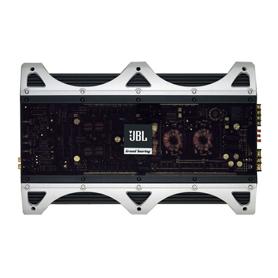
JBL GTO1201.1 Owner's Manual
Grand touring series car audio power amplifier
Hide thumbs
Also See for GTO1201.1:
- Owner's manual (8 pages) ,
- Owner's manual (8 pages) ,
- Owner's manual (14 pages)
Advertisement
Quick Links
Advertisement

Related Manuals for JBL GTO1201.1


Summary of Contents for JBL GTO1201.1
- Page 1 THANK YOU for purchasing a JBL Grand Touring® Series amplifier. In order that we may better serve you should you require warranty service for your new amplifier, please retain your original purchase receipt and return the enclosed warranty...
-
Page 2: Installation
We recommend listening at low or moderate levels while driving your car. JBL accepts no liability for hearing loss, bodily injury or property damage resulting from the use or misuse of this product. - Page 3 APPLICATIONS – GTO301.1, GTO601.1 AND GTO1201.1 The GTO subwoofer amplifiers are single-channel amplifiers. There are two sets of terminals to make it easy to connect multiple woofers. Either set of (+/–) terminals may be used when connecting woofers. To the right are two application diagrams to help plan your subwoofer system installation.
- Page 4 APPLICATIONS – GTO75.4 The GTO75.4 can be set up for stereo 4-channel, 3-channel or bridged 2-channel operation, as shown in Figures 6 through 8. NOTE: For simplicity, Figures 6 through 8 do not show power, remote and input connections. NOTE: Minimum speaker impedance for stereo operation is 2 ohms.
- Page 5 APPLICATIONS – GTO755.6 The GTO755.6 can be configured for Subwoofer Rear 6-channel, 5-channel or 3-channel oper- – – ation, as shown in Figures 9 through 11. NOTE: For simplicity, Figures 9 through 11 do not show power, remote and input connections.
-
Page 6: Installation And Setup
SETTING THE BASS BOOST The GTO755.6, GTO301.1, GTO601.1 and NOTE: After the source unit is on, red LEDs GTO1201.1 are all equipped with a bass- (on the top panel) will light, indicating the boost control. This allows you to adjust the amplifier is on. -
Page 7: Troubleshooting
INSTALLATION AND SETUP Figure 13. Installing neon tubes in a JBL GTO amplifier. TROUBLESHOOTING SYMPTOM LIKELY CAUSE SOLUTION No audio No voltage at BATT+ Check voltages at (POWER LED or REM terminals, amplifier terminals is off) or bad or no ground... -
Page 8: Specifications
• Dimensions (L x W x H): 475x313x60mm (18-11/16" x 12-5/16" x 2-3/8") JBL Consumer Products 250 Crossways Park Drive, Woodbury, NY 11797 USA © 2004 Harman International Industries, Incorporated JBL and Grand Touring are registered trademarks of Harman International Industries, Incorporated. Part No. GTOAMPOM10/04 www.jbl.com...