Advertisement
Quick Links
3-ZA20A, 3-ZA20B, 3-ZA40A,
3-ZA40B Zoned Audio
Amplifiers Installation Sheet
Description
The 20 and 40 watt zoned audio amplifier modules are key
components in emergency communication systems that consist of
audible and visible notification appliances. Models are available in
Class A and Class B versions. See Table 1 for a list of model numbers.
The amplifiers provide the following:
•
20 or 40 watts of power
•
Standard output line levels of 25 VRMS or 70 VRMS
•
A 1 kHz temporal (3-3-3) tone to use as an evacuation signal and
a 20 SPM tone to use as an alert signal in the event of a failure of
audio distribution
Each amplifier is also provided with an independently controlled
supervised, power limited 24 VDC NAC circuit. This facilitates the
addition of visual notification appliances to audio notification circuits.
Each zoned audio amplifier requires one space on the rail chassis
assembly.
Table 1: Models
Model
Description
3-ZA20A
20 watt zoned amplifier
Class A or Class B audio
Class A or Class B 24 VDC outputs
3-ZA20B
20 watt zoned amplifier
Class B audio
Class B 24 VDC outputs
3-ZA40A
40 watt zoned amplifier
Class A or Class B audio
Class A or Class B 24 VDC outputs
3-ZA40B
40 watt zoned amplifier
Class B audio
Class B 24 VDC outputs
© 2019 United Technologies Corporation
Installation
Install and wire this device in accordance with applicable national and
local codes, ordinances, and regulations.
Caution:
Operating the amplifier at an output greater than that
required by the speaker may overdrive the speaker circuit and result in
damage to the equipment.
To install the amplifier:
1. Remove all power from the panel.
2. Set jumpers JP1 and JP2 on the audio power module for 25 or
70 VRMS, depending on the input required by the audio circuit
speakers. See Figure 1.
JP1
25 VRMS
2 to 3
70 VRMS
1 to 2
3. Set the jumper on the audio amp transformer for 25 or 70 VRMS,
depending on the input required by the audio circuit speakers. See
Figure 1.
4. Slide the module into the required rail/slot position.
5. Gently push the module into the connectors to ensure good
contact.
6. Secure the module to the rail by pushing in the top and bottom
snap rivet fasteners.
7. Connect the field wiring. See Figure 2 through Figure 5.
Note:
The gain control pot (Figure 1) should be adjusted to the desired
output levels using a 1 kHz signal after installation. Fully counter
clockwise is maximum gain and fully clockwise is minimum gain.
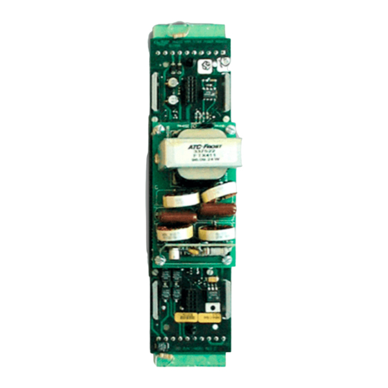
Figure 1: Jumper and gain control settings
(1) Front view
(2) Rear view
(3) Audio power module
(4) Audio amp transformer
1 / 4
JP2
2 to 3
1 to 2
(5) Configuration jumper
(6) Output gain control adjust
(7) Configuration jumpers
P/N 387463-EN • REV 005 • ISS 18MAR19
Advertisement

Summary of Contents for United Technologies Edwards 3-ZA20A
- Page 1 Class A or Class B 24 VDC outputs (4) Audio amp transformer 3-ZA40B 40 watt zoned amplifier Class B audio Class B 24 VDC outputs © 2019 United Technologies Corporation 1 / 4 P/N 387463-EN • REV 005 • ISS 18MAR19...
- Page 2 Wiring diagrams Figure 2: Typical 25 or 70 VRMS notification appliance circuit wiring Figure 3: Typical 24 VDC notification appliance circuit wiring Notes for Figure 2 and Figure 3 1. All wiring is supervised and power-limited. 2. Install listed 15 k Ω resistor on last device only when wired as Class B riser. 3.
- Page 3 Figure 4: Backup amplifier wiring Notes 1. All wiring is supervised and power-limited. 2. Backup amplifier must be rated greater than or equal to the other amplifiers to which it is connected and must be installed in the same enclosure. 3.
- Page 4 Specifications Regulatory information Current Environmental UL/ULC: Indoor dry Standby 62 mA class Alarm 1.12 A (3-ZA20A/20B) 2.48 A (3-ZA40A/40B) Contact information Frequency response 400 Hz to 4 kHz at ±3 dB For contact information, see www.edwardsfiresafety.com. Harmonic Distortion < 7% Audio circuit Input 8-channel, multiplexed digitized audio:...