Advertisement
Quick Links
LCB Pump Controller User Manual
Thank you very much for choosing our product. This product manual
provides important information and advice for product installation,
Before using this product, please read carefully and thoroughly
Our product has a number of safety and display functions.
The controller can be used in 12V and 24V systems has integral voltage
controller to limit the output voltage to max.of 12.0V or 24V
Max .16 mm² connector , Max safety current can reach 91A.
Self Test:
As soon as the controller is supplied with power from Panels, it starts a
self test routine. At the beginning, all LEDs flash twice, then Green LED
and Yellow LED are on.Then Controller starts to work with PWM output
for 5 seconds, then keeps output without PWM for 10 seconds. After Self
test, it continues to keep output until float switch on.if No connected to
load within 15 seconds ,the controller will be protected with red LED on.
Normally, The controller will be enabled when PV voltage rises above
14V(12V systems)/28V(24V systems). And disabled when PV voltage
downs to 11V/22V.
Controller has Automatic over current protection, low current protection
and low output voltage protection. When output current over 21A or short
circuit, or output current lower than 3A, or output voltage lower than
11V/22V, protection works with Red LED on. After 15 minutes, the
controller will retry to output..
Low Water Cut off :
The controller features a low water cut-off that will automatically cut
power to the pump when well water has been drawn down below the
pump of inlet, as well as dry-running(the controller detective output
current is 3A below, it will be dry-running)
Display Functions
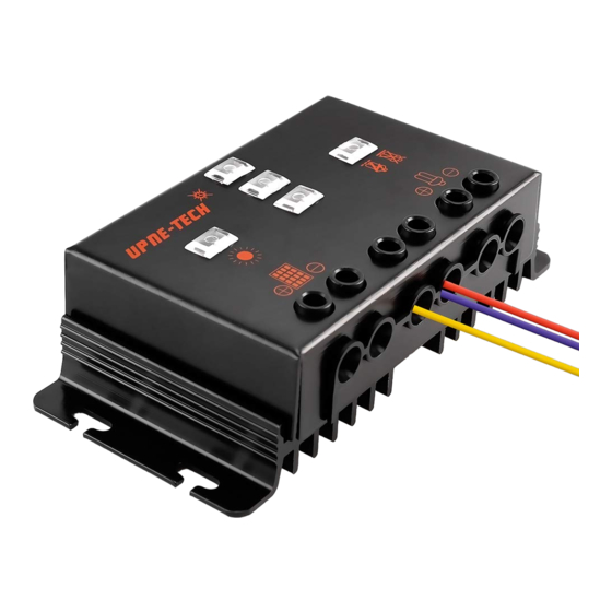
The controller is equipped with 3 LEDs
12V/24V Panel @/12V Pump, No connect to orang
Factory default
24V Panel@24 V Pump orange connect to PV-
LED
Status
Green/ Yellow
Flash twice
/Red LED
Green LED
On
Green LED
Off
Yellow LED
On
Red LED
On
Always Yellow Wire connect to the float switch wire, The other
float switch wire connect to the negative PV, the negative PV connected
to be grounded. If there is no float switch, please ignore the yellow wire
connection .
When the controller output power is low ,Please consider to add
lengthen the pipe of the pump until the input power and output power
are close.
When the rated current of the water pump exceeds 16A, the controller
needs to be fixed on a
heated
dissipate heat, otherwise it will cause thermal protection.
1
e wire to PV-
Function
Starting work
Solar array supplies electricity
Solar array does not supply electricity
Controller Normal operation
Float Switch on, Tank full
Over current(21A above) or short
circuit,or output current lower than
3A or No connected to load, After
fifteen minutes, Retry to output
metal so that the controller can better
Advertisement

Related Manuals for Upne-Tech LCB

Summary of Contents for Upne-Tech LCB
- Page 1 LCB Pump Controller User Manual 12V/24V Panel @/12V Pump, No connect to orang e wire to PV- Thank you very much for choosing our product. This product manual Factory default provides important information and advice for product installation, Before using this product, please read carefully and thoroughly Our product has a number of safety and display functions.
- Page 2 Solid LCB Technical Characteristics Model LCB 14A 16A 20A Rated system voltage 12V/ 24V Max.load current 14A 16A 20A Maximum output voltage 12 V(12V System) 24V(24V System) Start up Input-voltage 14V/28V Under panel voltage 11V/22V protection. Max. Input Panel voltage...