
Related Manuals for Harman Kardon AVR 500


Summary of Contents for Harman Kardon AVR 500
- Page 1 250 Crossways Park Drive, Woodbury, New York 11797 www.harmankardon.com © 1999 Harman Kardon, Incorporated Printed in China Part #1111-AVR500OM 6311-004-010...
-
Page 2: Avr 500 Audio/Video Receiver
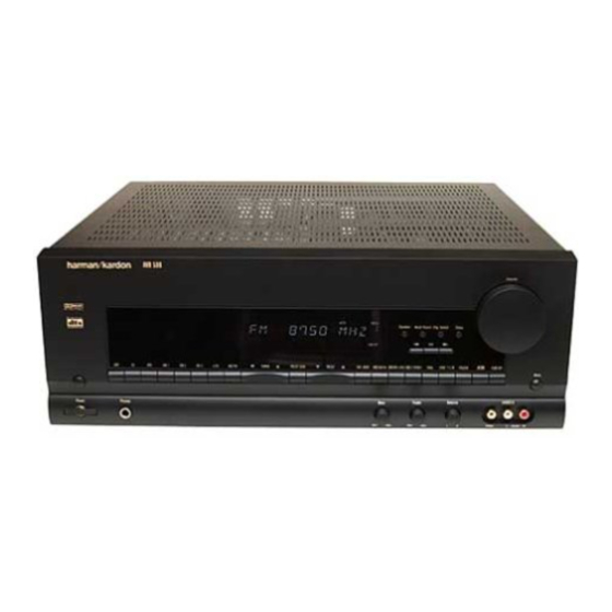
AVR 500 Audio/Video Receiver OWNER’S MANUAL AVR 500 Volum Speaker Multi Room Dig. Select Delay COAX DIGITAL TAPE VID 1 VID 2 VID 3 6 CH AM/FM TUNING PRESET SCAN PRESET TUN MODE DIGITAL PRO LOGIC 3-STEREO VMAx LOGIC 7 C/M THEATER SURR. -
Page 3: Table Of Contents
AVR 500 Audio/Video Receiver Introduction Safety Information Unpacking Front Panel Controls Front Panel Information Display Rear Panel Connections Remote Control Functions Installation and Connections System Configuration Operation Basic Operation Using the On-Screen Display Source Selection Surround Mode Selection Surround Mode Chart... -
Page 4: Introduction
DVD and LD releases and Digital Television broadcasts. While complex digital systems are hard at work within the AVR 500 to make all of this happen, hookup and operation are simple. Color-keyed connections, a backlit, programma- ble remote control, and on-screen menus make the AVR 500 easy to use. -
Page 5: Safety Information
Safety Information Important Safety Information Verify Line Voltage Before Use Your AVR 500 has been designed for use with 120-volt AC current. Connection to a line volt- age other than that for which it is intended can create a safety and fire hazard and may damage the unit. -
Page 6: Front Panel Controls
VMAx mode Selector Ò Logic 7 Mode Selector Ú Theater Mode Selector to turn on the AVR 500; press it again to turn the unit off. Note that the Power Indicator surrounding the switch 3 will turn green when the unit is on. - Page 7 6-Ch Direct inputs § as the listening source. $ AM/FM: Press this button to select the tuner as the AVR 500’s input source. When it is first pressed the last station tuned will be heard. Press it again to change between AM and FM bands.
-
Page 8: Front Panel Information Display
L Surround Off: This indicator illuminates when the surround processing has been dis- abled by pressing the Surround Off button Ù. When this indicator is lit, the AVR 500 will play traditional stereo sound using the front-left and front-right speakers only. -
Page 9: Rear Panel Connections
‹ Front Speaker Terminals › Center Speaker Terminals fi Surround Speaker Terminals fl Switched AC Outlet ‡ Unswitched AC Outlet ° AC Power Cord ° MODEL NO. AVR 500 AC ~ 120V 60 Hz HARMAN KARDON NORTHRIDGE CALIFORNIA, USA AC OUTLETS (120V.60Hz) TOTAL 150W or 1.5A MAX... - Page 10 100 watts. ° AC Power Cord: Connect the AC plug to a nonswitched AC wall output. · Remote IR Input: If the AVR 500’s front- panel IR sensor is blocked due to cabinet doors or other obstructions, an external IR sensor may be used.
-
Page 11: Remote Control Functions
AVR. Most buttons have additional functions when used with other devices. See page 30 for a list of these functions. 10 REMOTE CONTROL FUNCTIONS GUIDE 6 CH. VID1 VID2 AM/FM VID3 TUN-M MEMORY AVR 500 NIGHT MULTI-ROOM DIRECT CLEAR... - Page 12 Delay button has been pressed. h Channel-Select Button: This button is used to start the process of setting the AVR 500’s output levels to an external source. Once this buttons g to button is pressed, use the ⁄...
- Page 13 Sleep Button: Press this button to place the unit in the Sleep mode. After the time shown in the display, the AVR 500 will auto- matically go into the Standby mode. Each press of the button changes the time until turn-off in...
-
Page 14: Installation And Connections
3. Connect the output of any digital sources to the appropriate input connections on the AVR 500 rear panel. Note that the Optical and Coaxial digital inputs d e may be used with a Dolby Digital or DTS source or the output of a conventional CD or LD player’s... - Page 15 (composite) or S-Video signals. However, it will not convert signals from one video format type to the other. System and Power Connections The AVR 500 is designed for flexible use with multiroom systems, external control compo- nents and power amplifiers. Main Room Remote Control Extension...
-
Page 16: System Configuration
System Configuration When all audio, video and system connections have been made, there are a few configuration adjustments that must be made. A few minutes spent to correctly configure and calibrate the unit will greatly add to your listening experience. Speaker Selection and Placement The placement of speakers in a multichannel home-theater system can have a noticeable... - Page 17 You are now ready to power up the AVR 500 to begin these final adjustments. 1. Plug the Power Cable ° into an unswitched AC outlet.
- Page 18 For accurate calibration, it is a good idea to make these adjustments while seated in your favorite listening position: 1. Put the AVR 500 in the Dolby Pro Logic mode by pressing the Dolby Pro Logic Selector Ó on the front panel or by...
- Page 19 Information Display. If the sound from a speaker location does NOT match the position indicated in the display, turn the AVR 500 off using the Main Power Switch 1 and check the speaker wiring to make certain that each speaker is con- nected to the correct output terminal.
- Page 20 System Configuration To set the delay times, follow these steps: 1. Put the AVR 500 in the Dolby Pro Logic mode by pressing the Dolby Pro Logic Selector Ó on the front panel or by pressing the Surround Mode Selector on the remote, followed by the ⁄...
-
Page 21: Operation
• When using the AVR 500 for the first time, you must press the Main Power Switch 1 on the front panel to turn the unit on. This places the unit in a Standby mode, as indicated by the amber color of the Power Indicator 3 . -
Page 22: Source Selection
TV Monitor Video Output jack b and will be viewable on a TV monitor connected to the AVR 500. Make certain that your TV is set to the proper input to view the signal. Volume Control •... -
Page 23: Surround Mode Chart
Operation Surround Mode Chart MODE FEATURES DOLBY DIGITAL Available only with digital input sources encoded with Dolby Digital data. It provides up to five separate main audio channels and a special dedicated Low-Frequency Effects channel. Available only with digital input sources encoded with DTS data. Available on special DVD, LD and audio-only discs, DTS provides up to five separate main audio channels and a special dedicated low-frequency channel. -
Page 24: Digital Audio Playback
(HDTV) system. Note that an optional, external RF demodulator is required to use the AVR 500 to listen to the Dolby Digital sound tracks available on laser discs. Connect the RF output of the LD player to... -
Page 25: Tuner Operation
Main Information Display V or on-screen display. This is normal and does not indicate a problem with either the AVR 500 or the source machine. The AVR 500 will return to digital playback as soon as the data is avail- able and when the machine is in a standard play mode. -
Page 26: Tape Recording
The AVR 500 is equipped for future expansion through the use of optional, external adapters for formats that the AVR 500 may not be capa- ble of processing. When an adapter is connected to the 6-Channel Direct Input §, you may select it by pressing the 6-Ch Input Selector l # . -
Page 27: Multiroom Operation
Installation The key to remote room operation is to link the remote room to the AVR500’s location with wire for an infrared receiver and speakers or an amplifier. For complete installation instructions for Multiroom use, see page 14. Multiroom Setup... -
Page 28: Programming The Remote
Auto Search Method. Auto Search Method If the unit you wish to include in the AVR 500’s remote is not listed in the code tables in this manual or if the code does not seem to operate... -
Page 29: Programmed Device Functions
For example, button number 9 is the Test Tone but- ton for the AVR 500, but it is the “Favorite” button for many VCRs and Satellite receivers. Button number 34 is the Preset Tune Down but- ton for the AVR 500, the “Reverse Skip”... -
Page 30: Reassigning Device Control Selectors
For example, if you have two VCRs but no satellite receiver, you may program the “SAT” button to operate a second VCR. Before following the nor- mal programming steps for either Three-Digit... -
Page 31: Function List
Function List No. Button Name Tape AVR Selector CD Selector Power On Tape Selector Aux/DVD Selector Power On Power Off Power Off Sleep CDP Select Volume Up Input Level Up Mute Test Input Select Surround Select CDR Select Volume Down Input Level Down Channel Select ⁄... -
Page 32: Setup Code Tables: Tv
Setup Code Tables: TV Manufacturer/Brand Setup Code Number ADMIRAL AKAI AMPRO ANAM CANDLE CAPEHART CENTRONIC CITIZEN CLASSIC CONCERTO CONTEC CRAIG CROWN CURTIS MATHES DAEWOO DAYTRON DWIN DYNATECH ELECTROHOME EMERSON FISHER FUNAI FUTURETECH GOLDSTAR HITACHI INFINITY INKEL 31 SETUP CODES... - Page 33 Setup Code Tables: TV (continued) Manufacturer/Brand Setup Code Number JC PENNEY JENSEN KENWOOD KLOSS LUXMAN MAGNAVOX MARANTZ MEMOREX METZ MINERVA MITSUBISHI OPTONICA PANASONIC PHILCO PHILIPS PIONEER PORTLAND PROSCAN PROTON QUASAR RADIO SHACK 32 SETUP CODES...
- Page 34 Setup Code Tables: TV (continued) Manufacturer/Brand Setup Code Number REALISTIC RUNCO SAMPO SAMSUNG SANYO SCOTT SEARS SHARP SIGNATURE SONY SOUNDESIGN SUPRE MACY SYLVANIA SYMPHONIC TANDY TATUNG TECHNICS TECHWOOD TENIKA TERA TOSHIBA TOTEVISION UNIVERSAL VIDEO CONCEPTS VIDIKRON VIDTECH WARDS YAMAHA YORK ZENITH 33 SETUP CODES...
-
Page 35: Setup Code Tables: Vcr
ANAM AUDIO DYNAMICS BROKSONIC CANON CAPEHART CRAIG CURTIS MATHES DAEWOO DAYTRON DYNATECH ELECTROHOME EMERSON FISHER FUNAI GO VIDEO GOLDSTAR HARMAN KARDON HITACHI INSTANTREPLAY JC PENNEY JENSEN KENWOOD LLOYD MAGNAVOX MARANTZ MARTA MATSUI MEMOREX MINOLTA MITSUBISHI MULTITECH NORDMENDE 34 SETUP CODES... - Page 36 Setup Code Tables: VCR Manufacturer/Brand Setup Code Number OPTONICA PANASONIC PENTAX PHILCO PHILIPS PILOT PIONEER PORTLAND PULSAR QUARTZ REALISTIC RICO SAMSUNG SANSUI SANYO SCOTT SEARS SHARP SHINTOM SONY SOUNDESIGN SYLVANIA SYMPHONIC TANDY TATUNG TEAC TECHNICS TEKNIKA THOMAS TOSHIBA TOTEVISION UNITECH VECTOR RESEARCH VICTOR VIDEO CONCEPTS...
-
Page 37: Setup Code Tables: Cd
Setup Code Tables: CD Manufacturer/Brand Setup Code Number ADCOM AIWA AKAI CARVER DENON HARMAN KARDON KENWOOD MARANTZ MONDIAL NAKAMICHI ONKYO OPTIMUS PANASONIC PIONEER REALISTIC SHARP SHERWOOD SONY TEAC TECHNICS YAMAHA Setup Code Tables: DVD Manufacturer/Brand Setup Code Number DENON MAGNAVOX... -
Page 38: Setup Code Tables: Dvd/Ld
Setup Code Tables: DVD/LD Manufacturer/Brand Setup Code Number DAEWOO DENON GOLDSTAR KENWOOD MAGNAVOX OPTIMUS PANASONIC PHILIPS PIONEER REALISTIC SAMSUNG SHARP SONY TECHNICS TOSHIBA YAMAHA Setup Code Tables: CABLE Manufacturer/Brand Setup Code Number PIONEER AMERICAST JERROLD JERROLD PIONEER PIONEER SCIENTIFIC-ATLANTIC TOCOM ZENITH ZENITH Setup Code Tables: SAT... -
Page 39: Troubleshooting Guide
If the system still malfunctions, a system reset may clear the problem. To clear the AVR 500’s entire system memory including tuner presets, output level settings, delay times and speaker configuration data, first turn the unit off by pressing and releasing... -
Page 40: Technical Specifications
Height measurement includes feet and chassis. All features and specifications are subject to change without notice. Harman Kardon is a registered trademark, and Power for the Digital Revolution is a trademark, of Harman International Industries, Inc. *Manufactured under license from Dolby Laboratories.