Harman Kardon AVR 130 Owner's Manual
Audio/video receiver
Hide thumbs
Also See for AVR 130:
- Service manual (120 pages) ,
- Owner's manual (49 pages) ,
- Quick start manual (4 pages)

Related Manuals for Harman Kardon AVR 130


Summary of Contents for Harman Kardon AVR 130
- Page 1 Power for the Digital Revolution AVR 130 AUDIO/VIDEO RECEIVER OWNER’S MANUAL DIGITAL LOGIC 7 PRO LOGIC 3 STEREO 5 CH. STEREO SURR. OFF Surr. Select ® ® VID 1 VID 2 VID 3 FMAM TAPE 6 CH Coaxial...
-
Page 2: Table Of Contents
AVR 130 AUDIO/ VIDEO RECEIVER Introduction Safety Information Unpacking Front-Panel Controls Rear-Panel Connections Remote Control Functions Installation and Connections System Installation Audio Equipment Connections Video Equipment Connections Power Connections System Configuration Speaker Selection and Placement System Setup Speaker Setup Triple Crossover Setting... -
Page 3: Introduction
DVD releases and Digital Television broadcasts. While complex digital systems are hard at work within the AVR 130 to make all of this happen, hookup and operation are simple. Color-keyed connections and a programmable remote control make the AVR 130 easy to use. -
Page 4: Safety Information
SAFETY INFORMATION Important Safety Information Verify Line Voltage Before Use Your AVR 130 has been designed for use with 120- volt AC current. Connection to a line voltage other than that for which it is intended can create a safety and fire hazard and may damage the unit. -
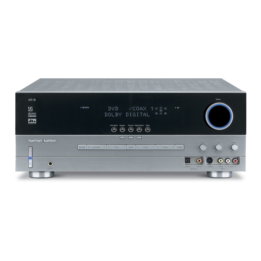
Page 5: Front-Panel Controls
Ô Video 3 Video Input Jacks Video 3 Audio Input Jacks AVR 130; press it again to turn the unit off. The Power Indicator 3 turns blue when the unit is on. 4 Headphone Jack: This jack may be used to listen to the AVR 130’s output through a pair of headphones. - Page 6 26.) Ù Volume Control: Turn this knob clockwise to increase the volume, counterclockwise to decrease the volume. If the AVR 130 is muted, adjusting the Volume Control Ù will automatically release the unit from the silenced condition.
-
Page 7: Rear-Panel Connections
¡ ™ £ ¢ ¡ CD Audio Inputs ™ Tape Outputs £ Tape Inputs ¢ Subwoofer Output ∞ Front Speaker Outputs § Surround Speaker Outputs ¶ Center Speaker Outputs • Optical Digital Inputs ª Coaxial Digital Inputs NOTE: To make it easier to follow the instructions that refer to this illustration, a larger copy may be downloaded from the Product Support section for this product at www.harmankardon.com. - Page 8 ⁄ Switched AC Accessory Outlet: This outlet may be used to power any device you wish to have turned on or off at the same time as the AVR 130. Any device connected to this outlet will be off when the AVR 130 is in the Standby mode, and power will be supplied to the outlet when the AVR 130 is turned on.
-
Page 9: Remote Control Functions
6-Channel Direct Input Button Mute NOTES: • The function names shown here refer to each button’s feature when used with the AVR 130. Most buttons have additional functions when used with other devices. See pages 31–32 for a list of these functions. -
Page 10: Remote Control Functions
AVR Selector: Pressing this button will switch the remote so that it will operate the AVR 130’s functions. If the AVR 130 is in the Standby mode, it will also turn the AVR 130 on. g AM/FM Tuner Select: Press this button to select the AVR 130’s tuner as the listening choice. - Page 11 ` Transport Controls: These buttons do not have any functions for the AVR 130, but they may be pro- grammed for the forward/ reverse play operation of a wide variety of CD or DVD players, and audio or video cassette recorders.
- Page 12 Direct Input a as the audio source. Mute: Press this button to momentarily silence the AVR 130 or TV set being controlled, depending on which device has been selected. When the AVR 130 is muted, press this button or use the Volume Control Ù...
-
Page 13: Installation And Connections
CD or LD player’s PCM (S/P-DIF) output. 4. Connect the Optical Digital Output ‹ or Coaxial Digital Output › on the rear panel of the AVR 130 to the matching digital input connections on a CD-R or MiniDisc recorder. -
Page 14: Power Connections
S-Video, or vice versa. S-Video inputs may only be viewed when the AVR 130 is connected to a TV set or video display with S-Video capability. If you use both standard composite video and S-Video sources in your... -
Page 15: System Configuration
You are now ready to power up the AVR 130 to begin these final adjustments. 1. Plug the Power Cord ‚ into an unswitched AC outlet. -
Page 16: System Setup
SYSTEM CONFIGURATION 5. Turn the AVR 130 on either by pressing the System Power Control 3 on the front panel, or via the remote by pressing the AVR Selector f or any of the Input Selectors eg on the remote. The Power Indicator 3 will turn blue to confirm that the unit is on, and the front- panel display will illuminate. -
Page 17: Triple Crossover Setting
“main” speakers. • If a subwoofer is connected to the AVR 130, you have the option to have the front left/right “main” speakers reproduce bass frequencies at all times, and have the subwoofer operate only when the... -
Page 18: Output Level Adjustment
SURROUND OFF appears in the Lower Display Line ¯ and the Surround Mode Indicator ˘ for Surr Off is lit, the AVR 130 will pass the analog source material directly through to the front left and right speakers, bypassing the digital-processing circuitry. -
Page 19: Delay Settings
The AVR 130’s advanced software enables you to quickly and easily set delay times without using a complex formula to calculate them. Instead, all you... - Page 20 Once the settings outlined on the previous pages have been made, the AVR 130 is ready for operation. There are some additional settings that may be made if desired, but these are best done after you have had an opportunity to listen to a variety of sources and dif- ferent kinds of program material.
-
Page 21: Operation
Bass Control Ó and Treble Control Ú to suit your listening tastes or room acoustics. • To set the output of the AVR 130 so that the output is “flat, ” with the tone controls deactivated, press the Tone Mode Button 5 until the words Tone Out appear momentarily in the Lower Display Line ¯. -
Page 22: Surround Mode Chart
The Surround Off (Bypass) mode may only be used with analog source DSP Surround Off inputs, as it preserves the analog format of the audio signal for its entire path of travel through the receiver to the speaker and subwoofer outputs, bypassing all digital processing. Digital bass management is not available in Surround Off mode. -
Page 23: Surround Mode Selection
DTS discs. You may use any LD or CD player equipped with a digital output to play DTS-encoded discs with the AVR 130. All that is required is to con- nect the player’s output to either the Optical or Coaxial input on the rear panel •ª or front panel... -
Page 24: Night Mode
DVD player (usually with the “Audio Select” button or in a menu screen on the disc) to send a full 5.1 feed to the AVR 130. It is also pos- sible for the type of signal feed to change during the course of a DVD playback. -
Page 25: Tuner Operation
7 M or Music mode for a wider soundstage and increased rear-channel ambience. Tuner Operation The AVR 130’s tuner is capable of tuning AM, FM and FM Stereo broadcast stations. Stations may be tuned manually, or they may be stored as favorite station pre- sets and recalled from a 30-position memory. -
Page 26: Output Level Trim Adjustment
OPERATION Output Level Trim Adjustment Normal output level adjustment for the AVR 130 is established using the test tone, as outlined on pages 18 and 19. In some cases, however, it may be desir- able to adjust the output levels using program material such as a test disc, or a selection you are familiar with. -
Page 27: Programming The Remote
Auto Search Method. Auto Search Method If the unit you wish to include in the AVR 130’s remote is not listed in the code tables in this manual or if the code does not seem to operate properly, you may wish... -
Page 28: Macro Programming
Function List and then look in the column for the device you are controlling. For example, button num- ber 51 is the Macro 2 button for the AVR 130, but it is the “Favorite” button for many cable television boxes and satellite receivers. -
Page 29: Volume Punch-Through
TV viewing, you may wish to have the AVR 130’s volume activated, although the remote is set to run the TV. Either the AVR 130 or TV volume control may be associated with any of the remote’s devices. - Page 30 Do not confuse these numbers with those used throughout the rest of this manual to indicate the specific buttons used to operate the AVR 130’s functions. The key to those button numbers, which are shown inside an oval, is found on page 9.
-
Page 31: Function List
No. Button Name AVR Function Power On Power On Power On Power Off Power Off Power Off Mute Mute Mute AVR Select DVD Input Select DVD Select CD Input Select Tape Tape Input Select VID1 Video 1 Select VID2 Video 2 Select 10 VID3 Video 3 Select 11 Dim... - Page 32 FUNCTION LIST No. Button Name AVR Function 44 Direct Direct Tuner Entry 45 Clear Clear Clear 46 Preset Up Preset Tune Up Slow Forward 47 Tune Down Tune Down Prev Chapter 48 D. Skip Disc Skip 49 Preset Down Preset Tune Down Slow Rev 50 M1 Open/Close...
-
Page 33: Setup Code Tables
CONTEC CORANDO CORONADO CRAIG CROWN CURTIS MATHES DAEWOO DAYTRON DIGI LINK DYNASTY DYNATECH ELECTROHOME EMERSON FUNAI FUTURETECH GOLD STAR/LG GRUNDIG HALL MARK HARMAN KARDON HITACHI INFINITY INKEL JC PENNEY JENSEN KAWASHO KENWOOD LLOYTRON LODGENET SETUP CODE TABLE: TV SETUP CODES... - Page 34 SETUP CODE TABLE: TV Manufacturer/Brand Setup Code Number LOGIK LUXMAN MAGNAVOX MARANTZ MATSUI MEMOREX METZ MINERVA MITSUBISHI NATIONAL NIKEI ONKING ONWA OPTONICA ORION PANASONIC PHILCO PHILIPS PIONEER PORTLAND PROSCAN PROTON QUASAR RADIO SHACK REALISTIC RUNCO SAMPO SAMSUNG SANYO SCOTT SEARS SHARP SIEMENS SIGNATURE...
- Page 35 018 048 DYNATECH EMERSON 013 040 042 110 112 FISHER FUNAI 076 095 124 GO VIDEO GOLD STAR/LG 018 107 HARMAN KARDON 018 049 HITACHI 040 048 JC PENNEY 018 045 JENSEN 018 048 111 132 KENWOOD 020 048 LLOYD...
- Page 36 SETUP CODE TABLE: VCR Manufacturer/Brand Setup Code Number MARANTZ MEMOREX 017 020 040 052 053 054 076 MITSUBISHI 049 131 MULTITECH NATIONAL 018 048 NORDMENDE OPTIMUS ORION PANASONIC 125 150 167 172 PHILCO PHILIPS 040 075 PORTLAND PULSAR QUASAR 001 125 RADIO SHACK 055 134 140 142 158 159 095 124 125 157 172...
- Page 37 AUDIOFILE CALIFORNIA AUDIO CAPETRONIC CARRERA CARVER 143 144 CASIO CLARINETTE DENON EMERSON FISHER FRABA FUNAI GENEXXA GOLD STAR/LG HAITAI HARMAN KARDON 054 190 HITACHI INKEL JC PENNEY JENSEN KENWOOD 079 148 LOTTE LUXMAN MAGNAVOX MARANTZ 192 193 MCINTOSH MITSUMI MODULAIRE...
- Page 38 WARDS YAMAHA YORK SETUP CODE TABLE: DVD Manufacturer/Brand Setup Code Number APEX DIGITAL DENON 019 051 003 004 GOLD STAR/LG HARMAN KARDON 005 055 064 066 MAGNAVOX MARANTZ MITSUBISHI ONKYO 009 048 PANASONIC 024 030 044 PHILIPS PIONEER 041 065...
- Page 39 Manufacturer/Brand Setup Code Number ALPHASTAR ALPHASTAR DBS ALPHASTAR DSR BIRDVIEW CHANNEL MASTER 320 321 CHAPARRAL 315 316 CITOH DRAKE 313 317 413 481 DX ANTENNA 331 352 379 483 ECHOSTAR 395 397 453 463 ELECTRO HOME FUJITSU 324 329 GENERAL INSTRUMENT 303 311 365 403 HITACHI DBS...
- Page 40 SETUP CODE TABLE: TAPE/CBL Manufacturer/Brand Setup Code Number HARMAN KARDON SETUP CODE TABLE: CBL Manufacturer/Brand Setup Code Number 001 011 ALLEGRO AMERICAST ARCHER BELCOR CABLE STAR 033 113 CITIZEN COLOUR VOICE 085 090 DIGI EAGLE EASTERN 066 070 ELECTRICORD EMERSON FOCUS G.I.
- Page 41 Manufacturer/Brand Setup Code Number REMBRANT SAMSUNG 072 186 SCIENTIFIC ATLANTA 183 203 221 222 SEAM SIGNATURE 001 188 SPRUCER 053 081 177 189 STARCOM 002 011 163 STARGATE TANDY TELECAPATION TEXSCAN TIMELESS TOCOM 170 205 UNITED CABLE UNIVERSAL 033 034 039 042 113 VIDEOWAY 124 211 VIEWSTAR...
-
Page 42: Troubleshooting Guide
Your AVR 130 receiver has been designed to provide many years of trouble-free service. In the event that you are experiencing difficulties, please check the suggestions below for a possible solution to your problem. Additional information on the AVR 130, including updated information and user hints, is available from our Web site at www.harmankardon.com. -
Page 43: Specifications
Height measurement includes feet and chassis. All features and specifications are subject to change without notice. Harman Kardon, Power for the Digital Revolution and Logic 7 are registered trademarks of Harman International Industries, Incorporated. * Manufactured under license from Dolby Laboratories. “Dolby, ” “Pro Logic” and the Double-D symbol are registered trademarks of Dolby Laboratories. - Page 44 ® 250 Crossways Park Drive, Woodbury, New York 11797 www.harmankardon.com © 2003 Harman International Industries, Incorporated Part No. CQX1A849Z...