Advertisement
Quick Links
BIS Z-GW-001-TCP
Subnet16™ TCP/IP Ethernet Gateway
INSTALLATION GUIDE
This document provides instructions and information designed
to assist users in the hardware setup of the Subnet16™ TCP/IP
Ethernet Gateway. For configuration details see the Gateway
Series Reference Manual.
The BIS Z-GW-001-TCP is designed to connect RFID
applications to a TCP/IP Ethernet network. The Gateway is an
Ethernet node which connects to a Host (PC or PLC) through
an Ethernet-compatible network cable.
It
supports
Subnet16™
Multidrop
bus
architecture,
subnetwork of up to sixteen processor stations, through an
RS485 interface connection.
The Ethernet port is also used for establishing a connection with
a computer running Windows for the purpose of configuring the
Gateway through the Dashboard™ Configuration Tool Utility
program.
TECHNICAL DATA
ELECTRICAL FEATURES
Power Supply
12 - 30 Vdc
DC Input Current max.
200 mA - 100 mA
Communication Interfaces:
Host
Ethernet TCP/IP
RFID Multidrop Readers
Subnet16™
(uses RS485 physical layer)
Configuration
Ethernet TCP/IP
Baud Rate
10/100 Mbps
ENVIRONMENTAL FEATURES
Operating Temperature
-20° to +50 ° C
(-4° to +122 ° F)
Storage Temperature
-20° to +70 ° C
(-4° to +158 ° F)
Humidity max.
90% non condensing
Vibration Resistance
14 mm @ 2 to 10 Hz;
EN 60068-2-6
1.5 mm @ 13 to 55 Hz;
2 g @ 70 to 200 Hz;
2 hours on each axis
Shock Resistance
30 g; 11 ms;
EN 60068-2-27
3 shocks on each axis
Protection Class
IP30
EN 60529
PHYSICAL FEATURES
Dimensions
100 x 107 x 32 mm
(3.9 x 4.2 x 1.3 in)
Weight
256 g (9 oz)
USER INTERFACE
LED Indicators
Power On, Subnet16™ Bus,
Ethernet TCP/IP,
Configuration Error
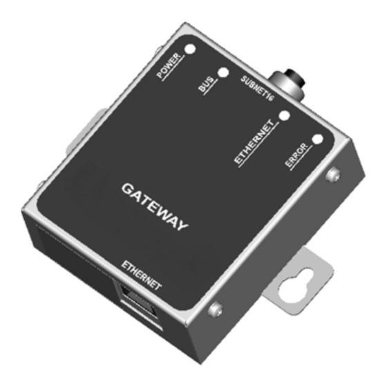
GENERAL VIEW
a
CONNECTIVITY
Ethernet
RJ45 Female Connector
5
4
BCC07WR
BCC07WR
BCC0ET0
BIS U-30X
BIS U-30X
6
6
See the Gateway Series Reference Manual for a complete list of accessories including alternative cables and connectors.
LED INDICATORS
The POWER LED is ON whenever
POWER
power is applied to the Gateway.
green
The BUS LED will flash ON and OFF to
indicate that data is being transmitted
Subnet16™
between the Gateway and one or more
BUS
amber
RFID Processors on the Subnet16™
network.
The ETHERNET LED will flash ON and
OFF to indicate that data is being
ETHERNET
transmitted between the host and the
amber
Gateway.
The Error LED is solid red when a
Gateway
ERROR
occurred, i.e. an invalid or unrecognized
red
command. This LED will be cleared
when a valid command is sent.
The AMBER LED on the left is the
10/100 Indicator LED, which will turn
ETHERNET
ON whenever an Ethernet link is
LINK
established and will remain ON for the
duration of the connection.
The GREEN LED on the right is the
Ethernet Data LED,which will flash ON
ETHERNET
and OFF when Ethernet traffic is
TRAFFIC
detected by the Gateway (regardless of
origin and destination).
Subnet16™
M12 5-pin Female Connector (Data and Power Supply)
PIN 4:
TX/RX+
PIN 3:
GND
Typical Layout
4
4
BCC07WR
BCC07WR
BCC0ET0
BCC0ET0
BCC06ZF
BIS U-30X
7
3
6
8
Vdc GND
to Ethernet Host
or Configuration PC
to Power Supply
HARDWARE REQUIREMENTS
The following components are required for a complete Subnet16™
RFID system:
•
One Subnet16™ TCP/IP Ethernet Gateway Interface Module
•
One host PC with an Ethernet network connection
•
One to 16 RFID Processors ( BIS M-41x, BIS M-62x or BIS U-
62x- Series Processors - RS485 models)
•
Adequate length cabling, connectors and terminators
•
A suitable power supply capable of providing sufficient power
to the Gateway and its RFID Processors via Subnet16™
network cabling
configuration
error
has
•
Balluff RFID data carrier or labels: BIS M-1xx or BIS U-1xx
INSTALLATION GUIDELINES
•
Do not route cables near unshielded cables or near wiring carrying
high voltage or high current. Cross cables at perpendicular
intersections and avoid routing cables near motors and solenoids.
•
Review the power requirements of your RFID network and provide
a suitable power supply.
•
Avoid mounting the Processor near sources of EMI (electro-
magnetic interference) or near devices that generate high ESD
(electro-static discharge) levels. Always use adequate ESD
prevention measures to dissipate potentially high voltages.
•
If electrical interference is encountered (as indicated by a
significant reduction in read/write performance), relocate the
Processor to an area free from potential sources of interference.
•
Perform a test phase by constructing a small scale, independent
network that includes only the essential devices required to test
your RFID application (use Balluff approved Subnet16™ cables
and accessories).
PIN 5:
TX/RX-
INSTALLATION
PIN 1:
SIGNAL
GND
The numbered steps in the following procedure are also indicated in
the Subnet16™ network example layout shown in the figure.
PIN 2:
1.
Preliminary Notes : Read this document in its entirety and note
VDC
the Installation Guidelines above.
2.
Mounting : Mount the Gateway to your chosen location using two
M5 (#10) screws, lock washers and nuts. The Gateway may be
mounted in any orientation, but should be aligned in such a
4
5
manner that the LED indicators can be seen during operation.
BCC07WR
3.
Gateway Connection : Attach one end of a 5-pin, male-to-male,
BCC0ET0
M12, ThinNet drop cable ( P/N: BCC0ET4 ) to the 5-pin, female,
M12 connector on the Gateway. Connect the other end of this 5-
pin, male-to-male, M12, ThinNet drop cable to the 5-pin, female,
M12 connector on a ThinNet to ThinNet Drop-T Connector (as
BIS U-30X
per your network and RFID application requirements).
4.
Trunk Wiring : Attach one end of a male-to-female trunk cable to
6
each mating connector on the Drop-T Connector. Continue
connecting trunk cables and Drop-T connectors as needed.
Note: trunk length should not exceed 300 m for ThickNet and 20 m
for ThinNet.
5.
Termination Resistors : For ThinNet Networks: Connect a
Terminating Resistor ( P/N: BCC09MR, male) to the first and last
Drop-T Connector on the trunk line.
(over)
Advertisement

Related Manuals for Balluff BAE00JM

Summary of Contents for Balluff BAE00JM
- Page 1 Series Reference Manual. Gateway configuration error • Balluff RFID data carrier or labels: BIS M-1xx or BIS U-1xx ERROR occurred, i.e. an invalid or unrecognized The BIS Z-GW-001-TCP is designed to connect RFID command. This LED will be cleared applications to a TCP/IP Ethernet network. The Gateway is an when a valid command is sent.
- Page 2 The maximum current rating for the Subnet16™ network using via Category 5e Ethernet cabling. A crossover cable may be Balluff cables and accessories (BCCxxxx), is 4.0 A . required if you are connecting the Gateway directly to a computer The following information is provided to assist you in (rather than to a switch, network hub or router).