Advertisement
Quick Links
READ & SAVE THESE INSTRUCTIONS! CAUTION:
• To prevent severe shock or electrocution, always
turn power OFF at the service panel before working
with wiring.
• Use this device with copper or copper-clad wire. Do
not use with aluminum wire.
• Must be installed in accordance with National and
Local electrical codes.
WARNING: IMPROPER WIRING OF ANY ELECTRICAL
DEVICE CAN CAUSE SERIOUS INJURY OR DEATH.
THESE WIRING DEVICES SHOULD BE INSTALLED BY AN
ELECTRICIAN OR OTHER QUALIFIED PERSON.
DESCRIPTION
The Radio Frequency (RF) Plug Load Controller expands the energy savings obtained from
traditional occupancy sensing to encompass AC receptacles as well as built-in lighting. We
accomplish this by providing an RF transmitter (WRC-TX or WRC-TX-LM) that connects to
your new or existing occupancy sensor, and a switched AC receptacle (WRC-15-x, WRC-20-x)
that contains a built-in RF receiver. When the RF Signal Pack receives an "vacancy" signal
from the sensor, it transmits a message commanding the receptacle to turn off. Similarly
when the office becomes occupied, the sensor sends a signal to the RF transmitter and the
receptacles turn on. Each RF Signal Pack can control up to 16 RF receptacles. A switched
feed through allows for control of downstream receptacles from a single RF receptacle.
Recommended communication range between RF Signal Pack and RF Receptacle is 30 feet.
Greater distances can be achieved in ideal environments.
RECEPTACLE INSTALLATION INSTRUCTIONS
1. After removing power as described above, use strip gage on back of outlet to strip
all wires to desired length (if not already stripped).
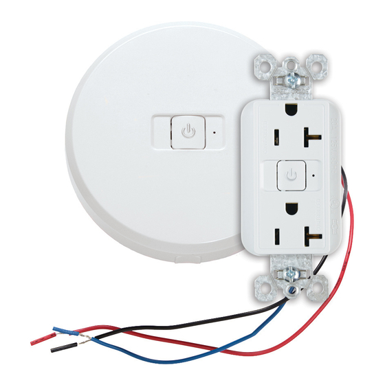
2. Attach wires according to the diagram below. Be sure the wires are fastened
securely either by the terminal screws or through the back-wire holes in the back
of the outlet.
Green or Bare Wire / Fil vert ou nu / Cable verde o pelado
Green Screw
Vis verte
Brass Screw
Tornillo verde
Vis en laiton
Tornillo de latón
White Screw
Vis blanche
Brass Screw
Tornillo blanco
Vis en laiton
Tornillo de
Not required if both
latón
faces are controlled
N'est pas nécessaire si les
deux faces sont contrôlées
No es necesario si se
controlan ambas caras
15A or / ou / o 20A
Controlled / Contrôlé /
Controlado
Hot / Sous tension / Vivo
125V
Neutral / Neutre / Neutro
250V
125V
WARNING: LOOSELY FASTENED WIRES MAY RESULT IN OUTLET FAILURE AND/OR
FIRE HAZARD.
If using terminal screws: Terminal screws accept up to #12 AWG wire. Wrap each
stripped wire 3/4 turn clockwise under heads of screws without overlapping and
tighten securely.
If using back-wire method: Back-wire accepts up to a #12 AWG wire. Insert stripped
wire between external pressure plate clamp and terminal. Tighten securely.
DESCRIPTION
La commande de charge de prise à fréquence radio (RF) accroît les économies d'énergie
obtenues grâce aux méthodes de détection de présence traditionnelles en incorporant
dans le système les prises CA ainsi que l'éclairage intégré. Ceci est effectué au moyen
d'un émetteur RF (WRC-TX) qui se branche à votre détecteur de présence (existant ou
nouveau), et une prise CA commutée (WRC-15-x, WRC-20-x), munie d'un récepteur RF
intégré. Lorsque le bloc de signal RF (l'émetteur) reçoit du détecteur un signal « d'absence
d'occupation », il transmet un message de commande pour mettre la prise hors tension. De
même, lorsque le bureau est à nouveau occupé, le détecteur envoie un signal à l'émetteur
RF et les prises sont mises sous tension. Chaque bloc de signal RF peut contrôler jusqu'à
16 prises RF. Une alimentation commutée permet le contrôle par une seule prise RF des
prises situées en aval. La portée de communication recommandée entre le bloc de signal RF
et la prise RF est de 9 m. Des portées plus importantes sont possibles dans des conditions
d'utilisation idéales.
Controlador para cargas comunes con alimentación CA
LIRE ET CONSERVER CES INSTRUCTIONS. ATTENTION
• Pour éviter tout choc électrique ou une électrocution,
coupez toujours l'électricité au niveau du panneau
d'alimentation avant de commencer à câbler.
• Utilisez ce dispositif avec des fils en cuivre ou cuivrés.
Ne l'utilisez pas avec des fils en aluminium.
• Doit être installé conformément aux codes locaux et
nationaux de l'électricité.
AVERTISSEMENT: LE CÂBLAGE INCORRECT DE TOUT
DISPOSITIF ÉLECTRIQUE PEUT CAUSER DES BLESSURES
GRAVES, VOIRE LA MORT. CES DISPOSITIFS DE CÂBLAGE
DOIVENT ÉTRE INSTALLÉS PAR UN ÉLECTRICIEN OU UNE
PERSONNE QUALIFIÉE.
Figure 1
Green Screw
Vis verte
Tornillo verde
Brass Screw
Vis en laiton
Tornillo de latón
White Screw
Vis blanche
Tornillo blanco
15A or/ ou/ o 20A
or / ou / o
INSTRUCTIONS EN FRANÇAIS
WRC-15-x, WRC-20-x
Radio Frequency (RF) Plug Load Controller
Commande de charge de prise à fréquence radio (RF)
LEA Y GUARDE ESTAS INSTRUCCIONES. PRECAUCIÓN:
ADVERTENCIA: EL CABLEADO INCORRECTO
DE UN DISPOSITIVO ELÉCTRICO PUEDE CAUSAR
LESIONES GRAVES O AÚN LA MUERTE. UN ELECTRICISTA
U OTRA PERSONA COMPETENTE DEBE INSTALAR ESTOS
DISPOSITIVOS DE CABLEADO.
3. Mount outlet in box using mounting screws supplied. Attach wall
plate. Restore power only when finished wiring the entire circuit.
PROCEDURE FOR BINDING
1. Press and hold BIND button on RF Signal Pack for 5 seconds until multi-
colored LED on RF Signal Pack flashes amber. All RF receptacles that are
not already bound to an RF Signal Pack will now flash green noting ready
to bind. Any RF receptacle already bound to this RF Signal Pack will flash
amber. Any RF receptacle out of range or bound to another RF Signal
Pack will not change state. If your RF receptacle is not flashing, reset to factory default
state by holding the receptacle BIND button for approximately 15 seconds until the
LED is a solid amber.
2. Press and hold BIND button on RF Receptacle for 2 seconds until LED on
receptacle flashes amber noting it is properly bound. If it was previously bound
to this RF Signal Pack (was flashing amber prior to holding BIND button for 2
seconds) it will unbind and flash green.
3. Repeat for all RF receptacles in room network.
4. Return to original RF Signal Pack and press and hold BIND button for 5 seconds
until flashing LED on RF Signal Pack turns off. All RF receptacles on the same
room network will stop flashing indicating Binding is complete.
5. Test that binding has been successful by tapping the push button of the RF Signal
Pack and confirm that the green led on the receptacles turn on and off.
OPERATING INSTRUCTIONS
The green LED on the receptacle is on when the outlet has power, and off when the outlet
is switched off. The bind button on the receptacle or the RF Signal Pack can be pressed to
override the occupancy sensor and turn on the receptacle temporarily.
This equipment complies with part 15 of the FCC Rules which are designed to provide
reasonable protection against harmful interference in a residential installation. This
equipment generates, uses, and can radiate radio frequency energy and, if not installed
and used in accordance with the instructions, may cause harmful interference to radio
communications. However, there is no guarantee that interference will not occur in a
particular installation. If this equipment does cause harmful interference to radio or
television reception, which can be determined by turning the equipment off and on, the user
is encouraged to try to correct the interference by one or more of the following measures:
• Reorient or relocate the receiving antenna.
• Increase the separation between the equipment and receiver.
• Connect the equipment into an outlet on a circuit different from that to which the
receiver is connected.
• Consult the dealer or an experienced radio/TV technician for help.
INSTRUCTIONS DE MONTAGE DE LA PRISE
1. Après avoir coupé l'alimentation tel qu'indiqué ci-dessus, utilisez le gabarit de
dénudement situé au dos de la prise pour dénuder tous les fils à la longueur souhaitée
(si ce n'est pas déjà fait).
2. Raccordez les fils comme indiqué dans la figure 1. Serrez correctement les fils au moyen
des bornes-vis ou dans les orifices arrière de fixation des fils au dos de la prise.
AVERTISSEMENT: DES FILS MAL SERRÉS PEUVENT PROVOQUER DES PANNES
ET DES INCENDIES.
En cas d'utilisation de bornes-vis : Les bornes-vis sont conçues pour des fils AWG
n° 12 maximum. Enroulez sans chevauchement la partie dénudée de chaque fil de
3/4 de tour dans le sens des aiguilles d'une montre sous les têtes de vis et serrez.
En cas d'utilisation de la méthode de fixation arrière des fils : La fixation arrière
des fils est conçue pour des fils AWG n° 12 maximum. Insérez la partie dénudée du
fil entre la borne et la vis de la plaque de pression externe. Serrez.
3. Montez la prise dans le boîtier à l'aide des vis de fixation fournies. Fixez la plaque
murale. Ne restaurez l'alimentation qu'après avoir câblé l'ensemble du circuit.
de radiofrecuencia (RF)
• Para evitar serios electrochoques o electrocución,
siempre APAGUE el suministro eléctrico en el panel
de servicio antes de trabajar con los cables.
• Utilice este dispositivo con alambres de cobre
o revestidos de cobre. No usar con cables de aluminio.
• Se debe instalar de acuerdo con los códigos
eléctricos nacionales y locales.
Advertisement

Summary of Contents for wattstopper WRC-15 Series
- Page 1 WRC-15-x, WRC-20-x Radio Frequency (RF) Plug Load Controller Commande de charge de prise à fréquence radio (RF) Controlador para cargas comunes con alimentación CA de radiofrecuencia (RF) READ & SAVE THESE INSTRUCTIONS! CAUTION: LIRE ET CONSERVER CES INSTRUCTIONS. ATTENTION LEA Y GUARDE ESTAS INSTRUCCIONES. PRECAUCIÓN: •...
- Page 2 (5) years. There are no obligations or liabilities on the part de cinq (5) ans. WattStopper ne peut être tenu responsable años. No existen obligaciones ni responsabilidades por of WattStopper for consequential damages arising out de tout dommage éventuel causé...