Advertisement
Quick Links
INSTALLATION AND OPERATION INSTRUCTIONS
VARIABLE HEAT CONTROL
FOR INFRARED HEATERS
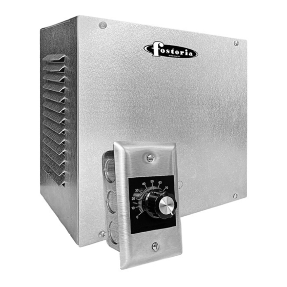
DESCRIPTION
The VHC-66 and VHC-99 are variable output controls for infrared heaters. The ouput can be adjusted
to allow the user to vary the desired output of the heater to maintain a comfortable environment
depending on the ambient temperature.
INSTALLATION
•
Disconnect power at main breaker before servicing this control.
•
The installation of the VHC-66 and VHC-99 must conform to the National Electric Code and/or
authorities having jurisdiction.
•
All wiring must be performed by a qualified, licensed electrician.
•
All conductors must be copper, the VHC-66 and VHC-99 must be grounded per the National Electric Code.
•
Over current must be provided to each indivdual heater circuit in an approved distribution panel.
•
The VHC-66 and VHC-99 are not rainproof, they must be installed in a protected area.
OPERATION
•
When all required installation and wiring are completed:
•
Adjust the potentiometer to the lowest setting (counter-clockwise).
•
Turn the breakers on.
•
Adjust the potentiometer (clockwise) to obtain the required heater ouput.
Note: These controls are provided with a three second ramp up function (soft start) to permit
control of high inrush lamps. Never connect cold lamps after start up.
FORM 8230
ISSUE DATE: 5/2021
VHC-66, VHC-99
VHC-66
Volts: 240/208
Amps: 32
Maximum watts@ 208V: 6656
Maximum watts@ 240V: 7680
Minimum Wire Size: 8 AWG
VHC-99
Volts: 240/208
Amps: 48
Maximum watts@ 208V: 9984
Maximum watts@ 240V: 11520
Minimum Wire Size: 6 AWG
ECO 1-7727
REV. LEVEL: --
INSTALLATION
INSTRUCTIONS
Hz:50/60
Hz:50/60
Page 1 of 3
Advertisement

Summary of Contents for Fostoria VHC-66
- Page 1 All wiring must be performed by a qualified, licensed electrician. • All conductors must be copper, the VHC-66 and VHC-99 must be grounded per the National Electric Code. • Over current must be provided to each indivdual heater circuit in an approved distribution panel.
- Page 2 WIRING AC POWER SOURCE SUPPLEMENTAL DISTRIBUTION PANEL SUPPLEMENTAL OVER CURRENT PROTECTION MUST BE SUPPLIED FOR EACH HEATER ORANGE YELLOW WARNING: The potentiometer is NOT ISOLATED; it is at line voltage potential. POTENTIOMETER MOUNTING 1/2"- 3/4" COMBINATION KNOCKOUT TOP & BOTTOM 10.0 CAUTION: Use hardware suitable for mounting...
- Page 3 POTENTIOMETER MOUNTING ENCLOSURE MOUNTING • Remove knock out in front cover. Install potentiometer as shown. WARNING: Potentiometer terminals are at line voltage. Disconnect power at main breaker before servicing. REMOTE MOUNTING • Install potentiometer as shown. Mount to a standard 2” x 4” electrical box. NOTE: Extension wire must be rated for line voltage 18AWG min., maximum 100 feet in length.