Table of Contents
Advertisement
Quick Links
Original Issue Date: 6/15
Model: RDT and RXT ATS with Load Management
Market: Residential/Commercial ATS
Subject: Power Relay Module Kit GM92001-KP1-QS
Introduction
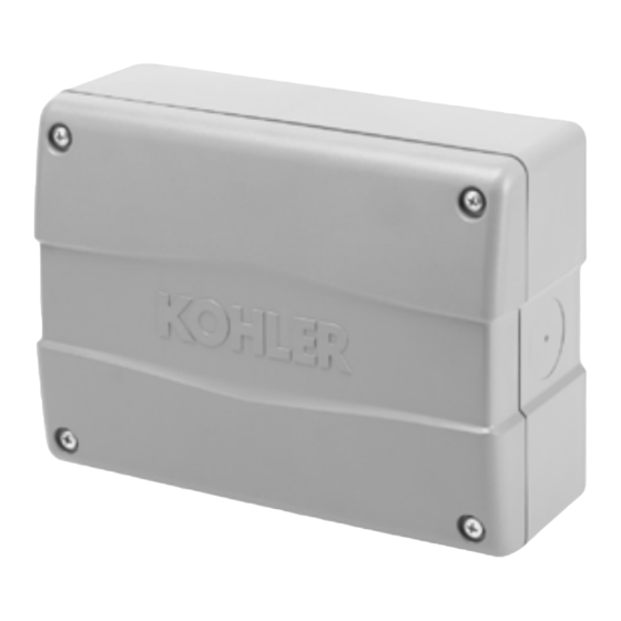
The power relay module kit contains one 50 amp relay
with connecting lugs in a NEMA type 3R enclosure. Use
up to four power relay module kits with the following load
management devices:
RDT automatic transfer switch with load shed kit
D
GM88281-KA1 or GM88281-KP1-QS
RXT automatic transfer switch with load shed kit
D
GM88281-KA1 or GM88281-KP1-QS
RXT automatic transfer switch with combined
D
interface/load management board
Note: A load shed kit or RXT combined interface/load
management board is required for load
management. See TT-1609 for the load shed kit
or TP-6807, RXT Operation and Installation
Manual,
for
load
information.
The power relay modules can be mounted indoors or
outdoors.
Mount the modules on a sturdy vertical
surface with the drain holes at the bottom of the module.
Two (2) 120 VAC loads (shed simultaneously) or a
single 240 VAC load can be wired to each relay.
An adequate electrical supply is required for operation
of the power relay module. The 120 VAC relays require
a customer-supplied voltage source.
electrical requirements of the customer-provided
equipment prior to installation to determine the wire size
and
circuit
protection
customer-provided equipment complies with applicable
local and national electrical codes.
Read the entire installation procedure and compare the
kit parts with the parts list at the end of this publication
before beginning installation. Perform the steps in the
order shown.
See Figure 1 for an illustration of the power relay
module.
INSTALLATION INSTRUCTIONS
management
operation
Check the
required.
Verify
that
Equipment Required
Two to four #8 screws to mount each module
D
Drill with 7/8 inch and/or 1 3/8 inch bits or hole saws
D
Level
D
Power cable for relay source and load connections
D
(see Specifications below)
Control cable for relay coil connection (see
D
Specifications below)
Conduit
D
If the modules are mounted outside, use outdoor-
d
rated conduit hubs .
If metal conduit is used, use conduit hubs with
d
screw terminals for the ground connection.
Figure 1 Power Relay Module
Specifications
Relay Rating
Operating Temperature
Storage Temperature
Relay Type
Coil Voltage
Control Relay Output
Connection (to relay coil)
Connecting Lug Wire Size
(qty. 4, relay source and load
connections)
Figure 2 Specifications
TT-1646 6/15
50 A @ 240 VAC
--20 to 55_C
(--4 to 131_F)
--40 to 85_C
(--40 to 185_F)
DPST -- NC
120 VAC
#6--32 screw
12--18 AWG cable
(ring terminals included)
#4--14 AWG
(Copper only)
Advertisement
Table of Contents

Summary of Contents for Kohler RDT ATS
- Page 1 TT-1646 6/15 INSTALLATION INSTRUCTIONS Original Issue Date: 6/15 Model: RDT and RXT ATS with Load Management Market: Residential/Commercial ATS Subject: Power Relay Module Kit GM92001-KP1-QS Introduction Equipment Required Two to four #8 screws to mount each module The power relay module kit contains one 50 amp relay with connecting lugs in a NEMA type 3R enclosure.
-
Page 2: Safety Precautions
Safety Precautions 1 Installation Procedure Observe the following safety precautions while installing Note: Load management priorities are determined by the kit. the relay connections to the load shed kit or interface/load management board. See TT-1609 for the load shed kit or TP-6807, RXT Operation WARNING and Installation Manual, for load priority and load management operation information. - Page 3 Connect the line side of the relay to the source power circuit as shown in Figure 4. This section applies to models RDT ATS and RXT ATS equipped with load shed kit GM88281-KA1 or b. Connect the load side of the relay to the GM88281-KP1-QS.
- Page 4 This section applies to the RXT ATS equipped with the combined interface/load management board. b. Connect the load side of the relay to the models RDT ATS and RXT ATS equipped with the load non-essential load circuits as shown in shed kit, go to Section 1.3.
-
Page 5: Operation
2 Operation 1.5 Ground the box. Note: The power relay module uses a non-conductive The power relay module operation is controlled by the resin enclosure. Bonding between conduit load management device, which is either a load shed kit connections is not automatic and must be or the RXT combined interface/load management provided as part of the installation. - Page 6 Figure 7 Power Relay Module Dimensions, ADV-8742, Sheet 1 of 2 TT-1646 6/15...
- Page 7 Figure 8 Power Relay Module Dimensions, ADV-8742, Sheet 2 of 2 TT-1646 6/15...
-
Page 8: Parts Lists
X-81-8 Installation Instructions TT-1646 Availability is subject to change without notice. Kohler Co. reserves the right to change the design or specifications without notice and without any obligation or liability whatsoever. Contact your local Kohlerr generator set distributor for availability.