Advertisement
Quick Links
Advertisement

Related Manuals for Bengtson Company Hanriot HD-1

Summary of Contents for Bengtson Company Hanriot HD-1
- Page 1 Hanriot HD‐1 38” Hanriot HD‐1 R/C Scale Model Instructions CONTACT INFORMATION The Hanriot HD‐1 was designed by M.K. Bengtson Manufactured and Distributed by: Bengtson Company e‐mail: sales@aerodromerc.com Web Site: www.aerodromerc.com Copyright© 2005‐11 M.K. Bengtson All Rights Reserved Rev 07/11 ...
-
Page 2: Power Setup
Hanriot HD‐1 38” Page 1 Hanroit HD‐1 slightly different from them. However, the concepts Thank you for purchasing the Hanriot HD‐1 model for illustrated are the same. electric flight. COWLING The cowling is of built up construction using C1 and C2. Model Built By M.K. Bengtson THE MODEL A semi scale adaptation of the Hanroit HD‐1, this model is designed to be easy to build and exciting to fly. POWER SET UP Cowl Construction Detail The model can be set up to be powered by the 6 v Speed 400 with the 2.33:1 Mini‐Olympus gearbox and a 10x4.7 Assemble the Cowling APC prop. Battery power pack is 8,600maH Nicads or an Construct front cowl ring by gluing 2 C1’s making sure equivalent weight Nimh that they are overlapping completely. To reduce weight, R/C GEAR the inner C1 may be shaved or sanded down after A four function mini receiver and four micro servos are all lamination. Maintain the inside of the part for proper that are required. construction. Glue 2 C2’s in three pairs and laminate SPECIFICATIONS together. More than 170 laser cut parts Scale: ~1/9 Channels: R/E/A/T Wing Area: ... -
Page 3: Fuselage Construction
Hanriot HD‐1 38” Page 2 WINGS Dihedral: Wing Construction Pin down, over the plan, the t/e, spars and wing tip, gluing as required. Add the leading edge stock after the basic frame is done as the stock is inserted in a rotated fashion. Add the wing tips and align the front tip along the center of the leading edge. Sand the leading edge stock to be rounded and meet the ribs. Wing Construction Detail FUSELAGE CONSTRUCTION The fuselage is built as two separate box structures, the front sheet area and the rear built up section, which are then joined over the plan. This system not only keeps each stage simple, but it also helps to ensure a straight fuselage. Building of the Right Side of the Fuselage Begin by building two rear fuselage frames over the plan Wing Construction Detail on Magnetic Building Board and allow to dry. Select hard balsa or basswood for the Leaning in the center ribs using the RAG: longerons. The Lower wings: Fuselage Construction Detail Join the two frames over the plan with cross braces and Wing Construction Detail the tailskid mount. Check, check and check again that this Ailerons: and ALL other structures remain perfectly straight and square. FUSILAGE CONSTRUCTION Wing Construction Detail ... -
Page 4: Tail Surfaces
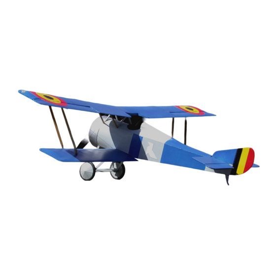
Hanriot HD‐1 38” Page 3 Front Side Panels Adding The Undercarriage Plates Front Side Panel Construction Detail Undercarriage Plates Remove from the board and add the plywood formers crosspieces that serve as u/c plates. Adding the Decking Add all the decking and formers, and carefully trim to size and fit 1/16” sheeting. Small pieces of 1/8” balsa are added next to the cabane struts before covering. Construction Detail Decking Construction Detail TAIL SURFACES Lay out and glue parts of the tail surfaces on the plans. Join the elevators with the 1/8” dowel joiner that is inserted into the carbon tube bearing. Sand the tail parts, rounding off all edges. Don’t add the horns or hinge the surfaces until after covering is complete. Construction Detail Tail Surface Construction Detail Copyright© 2005‐11 M.K. Bengtson All Rights Reserved Rev 07/11 ... - Page 5 Hanriot HD‐1 38” Page 4 Finished Model WHEELS Gluing the ply sides on the ¼ “balsa core makes the basis Tail Surface Construction Detail for the wheels. Use the brass hub for alignment. Epoxy the hubs in place and add a sufficient amount of epoxy around the base of the hub to reinforce the connection of the hub to the ply. Plywood reinforcing hubs are provided that are to slip over the brass tubing as shown. Alternatively, gluing an additional ½” square piece of scrap 1/8” balsa with a hole drilled in the center can be substituted. Next, CA glue the neoprene cording together to from a “tire”. Use thin CA sparingly as the CA bonds very aggressively to the rubber. Press the CA wetted ends Tail Surface Construction Detail together for an instant bond. The best way to align the ends is to glue them while they are in place on the wheel. Then attach the tires to the wheels and CA in place. A thin bead of CA around the rim makes for a secure tire. Paper cones are cut out. Use a ballpoint pen to score each line on the back to make an impression of “spokes”. It is helpful to do this operation on a paper tablet so that the pen makes a good crease. Fold the paper along the crease lines to exaggerate the raised lines. One of the sections forming a wedge is cut out. Make cuts to the center of the circle along a pair of the spokes. Close the paper cut‐out to form a cone and tape the joint inside the cone. Assembly Sand and dry fit to make the interplane struts. Be sure to mirror the opposing struts for proper wing installation. COVERING Any lightweight covering material can be used. Polyspan makes a good choice Litespan is also popular. This prototype was covered in Polyspan and painted with ...
- Page 6 Hanriot HD‐1 38” Page 5 hold the wheel in place and then the cone is attached. maintaining the neutral position of the aileron. This This method makes a very nice scale appearance. should counter any adverse aileron yaw. INSTALLING THE RADIO CONTROL GEAR Servo Bay It is as well to get the bulk of your R/C gear fitted at this stage, and also the motor. Mount all gear as far forward as possible to avoid C/G balance problems later. Battery Tray After all the above has been placed, mount the battery tray and use the battery position to balance the model as shown. ASSEMBLY . Top Wing Aileron Servo Installation Detail Wing The lower wings are added and the locating dowels are Landing Gear inserted into the fuselage. Apply epoxy to the wing rib The landing gear is fashioned from CA hardened 1/8” that meets the fuselage. Attach the wings to the fuselage. plywood. Sand, soak with thin CA and then, securely, Use the locating dowels to assist with aligning the wing epoxy the gear to the model. 0.045” music wire can be panels. Use a flat surface and sand bags to hold fuselage used to reinforce the gear but are not absolutely necessary. and lower wings in proper relationship. Lower wings If applied, use Kevlar thread or strong carpet thread and should not have any dihedral and be level with the secure the wire along the gear. CA in place. A shock bottom of the fuselage. Allow epoxy to set. Dry fit the top absorbing mechanism has been designed to let the model wing and make proper alignment using the interplane have a little give when landing. Attach the 1/16” music struts. Add epoxy in the sockets for the cabane and IP wire axle to the underside of the LG cross member with ...
-
Page 7: Contact Information
Hanriot HD‐1 38” Page 6 Rigging 3) Straight and non‐warped wings. 4) Be sure you assemble and lube the gearbox so that it Use strong thread or Kevlar fishing line to for rigging is not binding. A binding gearbox will rob most of wires. Elastic beading cord also makes excellent rigging your batteries power. and always stays taut. Use small screws, fishing hook eyes, straight pinheads or small eyelets to attach the CONTACT INFORMATION rigging. Alternately, brass wire (normally used for Distributed by: picture hanging) can be made into eyelets and CAʹed into Bengtson Company the model. While not technically required, rigging can add e‐mail: sales@aerodromerc.com a degree of strength to your model Web Site: www.aerodromerc.com Balancing the Model Balance the model at the point shown. It is best to position the battery to do this operation. Motor and Gearbox Tips The Mini‐Olympus gearbox is very durable and reliable but it does have a few weak points. 1) There is often flashing on the gears making rough spots or binding which robs power. Take a sharp Exacto knife and remove this until your gearbox turns smoothly. 2) Excess flashing also occurs where the motor is mounted that makes alignment poor and again robs power. Take the Exacto and carve away this excess until the motor fits easily. 3) Loose set screws on the main shaft and motor let power slip away. Tighten all these set screws ...