Advertisement
Quick Links
Installation Procedure
This product is optimized for use with Directed digital security and remote start
systems, such as DS4/DS4+. It is also fully compatible with most Directed ESP2
systems, as well as Autostart and AstroStart systems. Please read the following be-
fore proceeding.
1.
Customer Information required:
•
Record the customer information requested in step 4a of this procedure.
The module AirID # is provided on a sticker which can be affixed to the
space provided in the user guide.
This information is required for final verification/activation of the module.
2.
Installation Points:
•
Install and test the security/remote start system first using the associated
guides and wiring diagram. When adding SmartStart to an existing sys-
tem, verify it is fully functional before installing the SmartStart module.
•
DO NOT connect the SmartStart module until the final programming of
the Remote Start main unit and verification of security/remote start system
operations are completed.
•
For standalone SmartStart systems with no remote control, test the in-
stalled system via the SmartStart activation portal.
•
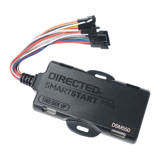
Mount the SmartStart module as high as possible in the vehicle with
"THIS SIDE UP" facing upward (for all devices). Mount with minimal
obstructions that can affect communications and within reach of the main
Directed system using the provided cables (do not extend).
CAUTIONS
The white 4-pin data connector is ONLY for Directed digital systems, such as
DS4/DS4+ or digital interfaces (DBALL2 and DB3).
There should NEVER be more than one data plug connected from the 3-way
cable adapter.
For some older analog systems with combined 4-pin ESP/D2D ports, you CAN-
NOT use an interface module in D2D mode when using a SmartStart module. You
must use W2W on the interface module.
DO NOT connect the black 3-pin ESP connector to white Door Lock port on
Directed systems.
3.
Install the module using the following information and the wiring diagram found
on this page (Note CAUTIONS during installation).
a.
Configuration Wires: Connect the loose gray or white configuration
wire(s) to match the desired application (see table below).
MODE
GRAY WIRE
WHITE WIRE
ESP2*
No Connection
No Connection
D2D, RSR/RXT**
GND
No Connection
Autostart/AstroStart
No Connection
GND
Analog
No Connection
GND
*
Directed Analog systems for Viper, Python, Clifford, Avital and
Automate.
** Directed digital systems.
b.
Connect the appropriate data connector to the correct port of the main
module. For D2D RSR/RXT applications, connect the serial data cable
and adapter to the Directed interface module.
c.
Complete the main power connections (if required).
d.
When power is connected, the module begins an initialization procedure
that normally takes a little over a minute. Weak cellular coverage or con-
Quick Reference Install Guide/
Guide d'installation à référence rapide/ Guía
Rápida de Instalación y Referencia:
DSM550, VSM550
gestion may cause the initialization to take longer. During this procedure,
progress is reported via the Orange/Green/White LEDs on the side of
the SmartStart module. For ESP2 and D2D applications, you must wait
until both the Orange and Green LEDs are on solid before proceeding
to activate and test the device in the installation portal. For Autostart or
AstroStart analog systems, only the Orange LED must be on solid (see the
LED Status Chart for a description of the various LED states).
4.
Verify and Activate the SmartStart module:
The following steps need to be performed for the verification/activation of the
Directed SmartStart module.
a.
Collect Customer Information:
Customer's E-mail Address:
Customer's mobile phone #:
Record/place Module ID # here:
New Account:
Existing Account:
b.
Log on to: www.directechs.com, and click on the SmartStart activation
link.
c.
Follow the on-screen directions to activate and test a SmartStart device.
The module's signal strength (RSSI) can be viewed in the activation portal after a successful
transmission test.
-50 to -90 dB
= good signal strength
-91 to -100 dB
= borderline/inconsistent signal strength
> -100 dB
= weak, insufficient signal strength
d.
Set configuration for commands to match the installed application.
e.
Test the SmartStart system from the website using the supplied function
links.
f.
To complete the activation process, assign the device to the customer
account using the email address collected in step 4a. The customer will
receive an e-mail that includes their account and device details, as well
as any additional steps they may need to follow in order to start using
their new system.
LED Status Chart
Orange LED
Off
No cellular communication. Check connections such as
module harness.
Blinking Slowly
The module is seeking cellular system communication. If no
cell coverage is available the Orange LED continues to blink
slowly, move the vehicle to a location with better reception.
Blinking Quickly
The module is negotiating with a cellular system.
Blink/Pause
The module is negotiating with the SmartStart server.
On Solid
Communication successfully established.
Green LED*
Off
Communication not established with ESP or D2D compatible
systems. Check connection at the ESP (Bitwriter) port or make
sure SmartStart is activated in your Digital system. Once
connected properly, power cycle the SmartStart and the LED
will turn on.
On Solid
Communication successfully established with the Directed
remote start or Directed digital system.
White LED*
Off
No GPS fix established.
Blinking
The module is seeking for GPS satellites.
On Solid
GPS fix acquired.
* The green LED does not light if connected to Autostart/AstroStart systems with
pager ports, or in standalone mode.
Note (DSM550/VSM550 only): In order to save power, all three LEDs are
switched to slow pulse mode after 2 hours of no activity. Also, when the de-
vice enters GPS sleep mode, all three LEDs are turned off completely. The radio
remains active in that mode, but the GPS receiver is cycled to reduce power
consumption. You may have to power cycle the module to check the LED status.
Note: SmartStart response time can vary depending on cellular coverage and net-
work congestion. Operating temperature range: -40°C/-40°F to + 70°C/158°F.
Wiring Schematic
Con guration Wires
(Gray & White) N/C
4 pins
THIS SIDE UP
LED
2 pins
not used
Orange (Network Status)
Green (Data
Connection)
White (GPS Status)
Con guration Wires (Gray & White)
Connect Gray wire to (-) Ground
4 pins
THIS SIDE UP
LED
2 pins
not used
Con guration Wires (Gray & White)
Connect Gray wire to (-) Ground
4 pins
THIS SIDE UP
LED
2 pins
not used
* Do not connect power and ground when using SmartStart
in a D2D con guration or damage may occur.
Wiring Table
6-pin Analog Output Cable
Pin #
Wire Color
Connection/Description
1
White/Blue
-
(
) Remote Start Activation AUX output (200mA)
-
2
Brown/Black
(
) Alarm input
3
Green
-
(
) Lock output (200mA)
-
4
Blue
(
) Unlock output (200mA)
5
Red/White
-
(
) Trunk output (200mA)
6
Brown/White
+
(
) Alarm input
Notes:
•
The analog output wires are only active if the device has been configured for
Analog Wire mode in the installation portal.
•
For Analog Wire mode, please make sure the white wire is connected to
ground.
Directed
Analog Cable (6 pins, see table)
Analog System
ESP (4 pins, Brown)
(Top View)
or
ESP (3 pins, Black)
D2D N/C
(4 pins, White)
Fuse
Red: +12V *
Black: Ground *
DB3
Analog Cable (6 pins, see table)
(Top View)
ESP (4 pins, Brown)
or
ESP (3 pins, Black)
SmartStart
Cable
D2D
(4 pins, White)
Fuse
Red: +12V * N/C
Black: Ground * N/C
Analog Cable (6 pins, see table)
ESP (4 pins, Brown)
or
ESP (3 pins, Black)
Directed
SmartStart
Digital System
Cable
(Top View)
D2D
(4 pins, White)
Fuse
Red: +12V * N/C
Black: Ground * N/C
QRNDSM550-VSM550, 510-10653-01 (R1.2)
Advertisement

Related Manuals for Viper DIRECTED SMARTSTART PRO DSM550


Summary of Contents for Viper DIRECTED SMARTSTART PRO DSM550
- Page 1 The module is negotiating with a cellular system. Directed Analog No Connection SmartStart Digital System Blink/Pause The module is negotiating with the SmartStart server. Directed Analog systems for Viper, Python, Clifford, Avital and Cable (Top View) THIS SIDE UP 2 pins Automate. On Solid Communication successfully established.