Advertisement
Available languages
Available languages
Quick Links
A
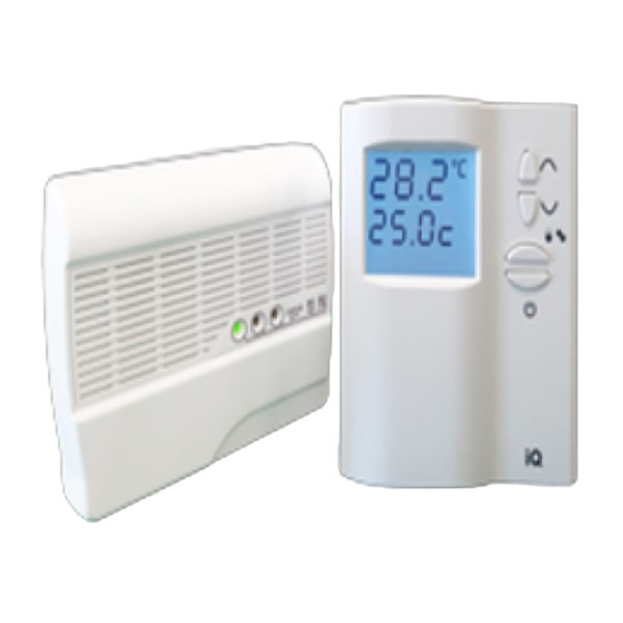
T10
Electronic Room Thermostat for Heating
Τ20
Electronic Room Thermostat with Domestic Hot Water Switch
Τ10SW
Electronic Room Thermostat for Heating and Cooling
Installer's and User's Manual
Important Safety Information
• Read carefully the information included in this manual.
• Always switch off the main power when installing the thermostat.
• The installation should be carried out by authorized personnel.
• Do not use the thermostat for other applications except those that is made to be used
i.e. room heating
• This thermostat is not an instrument. It must not be used in life critical applications.
Installation
Install the thermostat always in an inside wall in height 1.2m to 1.5m from the floor and
away of corners, positions affected of heat generating appliances, air vents , places directly
exposed to sunlight or dead air spots (e.g. behind a door, curtain etc.).
Consult the figures 1 to 6 printed at the carton box for dismantling and reassembling the
thermostat.
Before reinstall the rotating knob you can restrain the allowable adjust range by utilizing
the two plastic pins underneath.
Wiring
Connect the appropriate wires to cable terminal strip as shown in the relative wiring
diagram in the electrical connection section below.
As every electronic equipment this thermostat requires power to operate. Connect mains
phase 230VAC/50Hz to "L" and neutral to "N" terminal.
Terminals "A" and "1" comprise the potential free contacts of the internal relay. In case
phase control output is needed for the heating (or cooling) system terminals "L" and "A"
must be wired together.
Operation
The "O‐I" signed sliding switch of the front face activates and deactivates the thermostat.
While in on position "I" thermostat controls the heating (or cooling) system to maintain the
desired temperature.
Adjust the rotating button to the temperature level of your choice. When temperature
differs as compared to that indicated by the rotating knob the green indicator lights on and
the contact of the internal relay closes. When the desired temperature is reached the relay
contact opens and the green indicator remains inactive.
The leftmost sliding switch of T20 type activates the domestic hot water control output
(terminal "2") which is always phase. At the same time the red indicator lights on.
The leftmost sliding switch of T10SW type is used to select between heating or cooling
mode. The "
" symbol indicates cooling mode and when selected the red indicator lights
on.
This thermostat meets the accuracy and other technical specifications approximately 3
minutes after it is switched on.
Electrical Connection
General electrical connection diagram
Electrical connection diagram for systems which have ~230VAC control input
* For heating or cooling systems with ~230VAC control inputs wire together "L" and "A"
terminals.
This product has been manufactured from materials which can be recycled
and reused according to the European Directive 2002/96/EC.
Please be informed regarding the local collection system for electrical and
electronic equipment and do not dispose the old products with your
normal household waste.
The correct disposal of the products will help to prevent the negative
consequences of the environment and human health.
Technical Specifications
Physical dimensions
Mains power
Electrical contact rating
Auxiliary contact rating
Adjust limits
Differential
Temperature accuracy
Operating temperature
Storage temperature
90 x 90 x 43mm approx.
~230VAC/50Hz ±10%
5A/250VAC @resistive load, (3A@inductive load)
2A
0 °C to +30 °C
‐0.4°C
+/‐0.5°C
‐10 °C to +50 °C
‐20 °C to +50 °C
Customer Care
Charmeg
www.charmeg.gr
27 Kotronos str. Aegaleo‐ Athens‐ Greece
Call: +030 210 5693111
Fax: +030 210 5693093
e‐mail: info@charmeg.gr
Skype: Charmeg Live Assistance Europe
Doc: T10_T10SW_T20_Users_Manual_gr_en_2.docx 2‐Mar‐10
Advertisement

Related Manuals for Charmeg T10


Summary of Contents for Charmeg T10
- Page 1 Electrical Connection Customer Care General electrical connection diagram Charmeg T10 www.charmeg.gr 27 Kotronos str. Aegaleo‐ Athens‐ Greece Electronic Room Thermostat for Heating Τ20 Call: +030 210 5693111 Electronic Room Thermostat with Domestic Hot Water Switch Fax: +030 210 5693093 e‐mail: info@charmeg.gr Τ10SW Skype: Charmeg Live Assistance Europe Electronic Room Thermostat for Heating and Cooling Installer’s and User’s Manual Electrical connection diagram for systems which have ~230VAC control input Important Safety Information • Read carefully the information included in this manual. • Always switch off the main power when installing the thermostat. ...
- Page 2 Ο αριστερός διακόπτης της πρόσοψης που υπάρχει στον τύπο Τ10SW χρησιμοποιείται για Υποστήριξη Πελατών να επιλεγεί η λειτουργία θέρμανσης ή ψύξης. Το σύμβολο “ ” σημαίνει ότι έχει επιλεγεί η λειτουργία ψύξης. Ταυτόχρονα η κόκκινη ενδεικτική λυχνία ανάβει. Charmeg Ο θερμοστάτης επιτυγχάνει την ακρίβεια και τις άλλες προδιαγραφές λειτουργίας του T10 περίπου 3 λεπτά αφότου τεθεί σε λειτουργία. www.charmeg.gr Κότρωνος 27 Αιγάλεω‐ Αθήνα ‐Ελλάδα Ηλεκτρονικός Θερμοστάτης Χώρου για Εγκαταστάσεις Θέρμανσης Διαγράμματα Ηλεκτρικών Συνδέσεων Τ20 Τηλ: 210 5693111 Ηλεκτρονικός Θερμοστάτης Χώρου για Εγκαταστάσεις Θέρμανσης με Διακόπτη Φαξ: 210 5693093 Γενικό ηλεκτρολογικό διάγραμμα e‐mail: info@charmeg.gr Ζεστού Νερού Χρήσης Skype: Charmeg Live Assistance Europe Τ10SW Ηλεκτρονικός Θερμοστάτης Χώρου για Εγκαταστάσεις Θέρμανσης και Ψύξης Εγχειρίδιο Εγκατάστασης και Χρήσης Οδηγίες Ασφαλείας ...