Advertisement
Quick Links
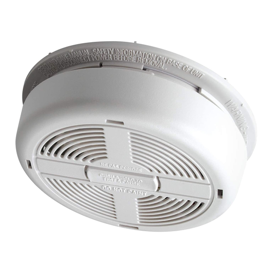
M A I N S
SMOKE ALARMS
& HEAT ALARMS
OWNERS
MANUAL
COVERS • Simple Fitting Instructions • Location Guide
For further information
please write:
Dicon Safety Products (Europe) Ltd.
P.O. Box 402
GLOUCESTER
650M, 650MC, 650MRB 650MRL, 650MBX
GL2 9YB
680M, 680MC, 680MRL, 680MRB, 680MBX
2502-A0033
CHECKS BEFORE USE
370MBX, 650MBX, 670MBX, and 680MBX:
• Check battery has been fitted correctly.
• Check alarm is not beeping.
• Test alarm before switching on the electricity supply.
• Check the green light is on (behind the front grille).
• Check the red light flashes every 45 seconds or so.
• When testing linked alarms check that they all
interconnect within 10 seconds.
IMPORTANT NOTES
• On the 370MBX the alarm will beep for 10 minutes
if the pause button has been pressed.
• Alarms with rechargeable batteries or capacitor
back up may beep for up to 2 hours while the
batteries / capacitors charge.
• Leave a copy of this handbook with the user and ensure
they know how to use and maintain the alarm.
P O W E R E D
• User Information • Basic Fire Safety Tips
• Simple Maintenance Instructions
MODELS:
PHOTOELECTRIC SMOKE ALARMS
IONIZATION SMOKE ALARMS
670M, 670MC, 670MRB, 670MRL,
670MBX, 370MBX
HEAT ALARMS
220-240VAC (
)
MAINS POWERED ALARMS
CLASS II APPARATUS
IMPORTANT: PLEASE READ
AND RETAIN THIS OWNERS MANUAL
When installing this alarm for use by others, please
leave this manual or a copy with the end user.
All Alarms:
A: GUIDANCE ON INSTALLATION
WARNING: Wiring should be installed by a qualified electrician in accordance with BS7671.
Permanent connection to the fixed wiring of the building should be made in a suitable junction box.
This alarm must not be exposed to dripping or splashing. Connect the alarm as late as possible in
an installation, particularly in new build, to avoid contamination. Remove the dust cover before
applying power.
NOTE: For detailed guidance on the siting of this alarm refer to section C of this handbook.
IMPORTANT: The circuit used to power the alarm must be a 24 hour voltage circuit that cannot be
turned off by a switch. BS5839 Part 6 states that: -
For mains powered alarms, each with an integral standby supply (Grade D), the mains electricity
supply should take the form of either:
a) an independent circuit at the dwelling's main circuit board, in which case no other electrical
equipment should be connected to this circuit (other than a dedicated monitoring device
installed to indicate failure of the mains electricity supply to the alarms); or
b) a separately electrically protected, regularly used local lighting circuit.
For mains powered alarms, with no standby supply (Grade E), the mains electricity supply may
only take the form of an independent circuit as per a) above. If it is necessary to use an RCD for
protection, it should operate independently of any RCD protection for circuits supplying sockets or
portable equipment.
All interconnected alarms should be installed on a single final circuit.
NOTE: The maximum interconnect wiring length is 250 metres. The maximum number of alarms
interconnected together is 12. Dicon smoke alarms should not be connected to any model
produced by another manufacturer.
The location of the alarms must comply with the applicable building codes and the advice in
section C: WHERE TO LOCATE below.
B: INSTALLATION (See Diagrams 1 & 2)
1. IMPORTANT INFORMATION: THE COLOUR CODING FOR ELECTRICAL CABLES USED IN
BUILDING WIRING HAS BEEN CHANGED AS FOLLOWS:-
Old colour
New (harmonised) colour
Red
Brown
Yellow
Black
Blue
Grey
Black
Blue
The new (harmonised) colour cables may be used on site from 31 March 2004. New installations
or alterations to existing installations may use either new or old colours, but not both, from 31st
March 2004 until 31st March 2006. Only the new colours may be used after 31 March 2006. For
more information see Amendment No: 2 to BS 7671:2001 and guidance publications.
See also www.iee.org/cablecolours
When selecting cable for connecting interlinked
smoke alarms the interlink wire should be
treated as live.
2. Use either of the methods of installation
shown in diagrams1 and 2.
The installation method shown in diagram 1 is
suitable for a plasterboard or similar ceiling
where access to the void behind it is available
and suitable to mount the junction box.
The installation method shown in diagram 2 is
suitable for concrete or similar ceilings where
access is insufficient or where surface wiring
is necessary.
3. Connect the brown wire to the brown (live)
in the house wiring and the blue wire to the
blue (neutral). NO CONNECTION SHOULD
BE MADE TO THE MAINS ELECTRICITY
SUPPLY EARTH TERMINAL. TERMINATE
HOUSE WIRING EARTH
IN SPARE CONNECTOR.
4. For multiple alarm installations use a "three
core and earth" style cable between all the
alarms to be interconnected and connect
the third core of that cable to the white wire from the smoke alarm. DO NOT use the earth wire
for the interconnect line. This must be treated as live, i.e. insulated and sheathed. If the alarm
is not going to be interconnected, cap the unused wires.
5. Remove the baseplate from the back of the alarm by twisting anti-clockwise as far as it will go.
(about 12 mm). Detach the locking pin.
Designation
L1 (Live)
L2 (Live)
L3 (Live)
Neutral
BROWN (LIVE)
Diagram 1
BLUE (NEUTRAL)
BLACK or GREY (INTERLINK)
EARTH
JUNCTION BOX
BASEPLATE
BROWN
WHITE
BLUE
ALARM
BATTERY
ACCESS
DOOR
INSTALLATION USING JUNCTION BOX
650M
Detac
Open
conne
with t
to the
Test t
6. Attac
tighte
or jun
7. Bring
openi
IMPORTA
BE FITTED
AND THE
ALARM F
DUST AN
OF THE A
with prote
8. Plug t
9. Place
arrow
twist
To se
lockin
into t
on th
370M
Open
conta
and te
Fit eit
the al
close
drawe
LOCK
THE B
10. Switc
11. Chec
The li
12. Press
butto
SYSTEMS
Test each
seconds.
WARNING
Do not at
may dam
The dust
chances
Remove t
equipmen
C: WHE
1. As a m
of fire
smoke
accom
one sm
with tw
each s
installe
and on
and lan
NOTE: He
only be u
interconn
2. Additio
caused
Advertisement

Related Manuals for Dicon 650M


Summary of Contents for Dicon 650M
- Page 1 NOTE: The maximum interconnect wiring length is 250 metres. The maximum number of alarms arrow HEAT ALARMS interconnected together is 12. Dicon smoke alarms should not be connected to any model twist 680M, 680MC, 680MRL, 680MRB, 680MBX produced by another manufacturer.
- Page 2 Turn off the mains electricity supply. Remove the locking pin by inserting a small screwdriver into Your Dicon Ala the square hole at the top of the battery drawer. Apply pressure at the tip of the screwdriver, 4.