Advertisement
Available languages
Available languages
Quick Links
TM11A01KNXFI04030001.doc
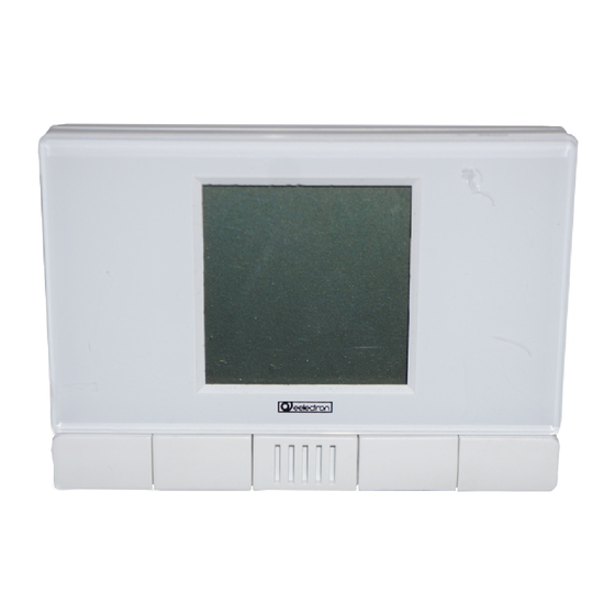
Inwall Room Thermostat
TM11A01KNX –Light Grey
TM11A11KNX – Dark Grey
TM11A21KNX – White
Product and Applications description
The Inwall Room Thermostat TM11A01KNX is an EIB/KNX
wall mounting device designed for HVAC applications in Home
and Building installations (i.e. offices, hospitals, hotels, private
houses, etc..).
Do
not
install
in bathrooms, swimming
pools and similar environments.
The device is equipped with one binary input (potential free
contact) that can be used, for instance, to control the HVAC
units whether a window has been opened (or closed) or for a
general purpose usage and one binary output relay to control
fan coils or for any different purposes.
The LCD on the front side displays the following information:
•
Actual temperature from 0 to 50.0 ° C (or ° F)
•
Fan coil speeds
Thermostat current status
•
The control elements available on the front are:
•
A push button to increase the temperature setpoint
A push button to decrease the temperature setpoint
•
A push button to increase the fan coil speed
•
A push button to decrease the fan coil speed
•
The device configuration for commissioning in terms of physi-
cal address, group addresses and parameters is done with
ETS ( Engineering Tool Software) through a download of the
Application Program.
Display and Icons
Cooling Mode
Night Mode
(Economy)
Thermostat OFF
Guest in Room / Stand-by Mode
Fan Coil speeds
Application Program
Downloadable from eelectron website: www.eelectron.com
Dati tecnici
Power Supply
•
Via bus EIB/KNX cable
Do not connect input/output with voltages different
than specified
Inputs
Number: 1 potential free contact
•
Input signal voltage Vn = 5 V
•
Input signal current at close contact = 1mA
•
Outputs
Number: 1 relays NO 24 V AC/DC, 1A (AC1)
•
Do not connect relays to mains (230V)
Control Elements
1 programming push button (back side)
•
•
1 push button to increase temperature setpoint
1 push button to decrease temperature setpoint
•
1 push button to increase fan coil speed
•
1 push button to decrease fan coil speed
•
Mounting instructions
1
Display Elements
•
1 LED red (back) for ETS programming
•
1 LCD display B/W, size 43,5X43,5 mm
Connections
• Bus line:
bus terminal connector block, single core max 0,8mm Ø
• Output relay
Screw terminal block
Conductor cross section max.1,0 mm
• Input signal (potential free)
Screw terminal block
Conductor cross section max.1,0 mm
Max cable length: 10 meters
Wiring Diagram
Physical specifications and Dimensions
• Housing: plastic
• Colours: Light Grey
Dark Grey
White
• Dimensions: (W x H x D): 110 x 78 x 39,8 mm
• Weight: approx. 80 g.
• Installation: Flash mounting in 2 or 3 modules or wall round
box Ø60mm, 40mm deep
Heating Mode
Electrical Safety
• Pollution degree : 2 (according to EN 60664-1)
Automatic
• Protection class IP20 (according to EN 60529)
Mode
• Safety class: II (according to EN 61140)
• Overvoltage category: III (according to EN 60 664-1)
Antifreeze
• Bus: safety extra low voltage SELV DC 24 V
• Device complies with EN50491-3 e EN60730
Electromagnetic compatibility
Complies with EN50491-5 e EN60730
Environmental specifications
• Climatic conditions: complies with EN 50491-2
• Ambient operating temperature: 0° C + 50° C
• Storage temperature: - 20 + 55 °C
• Relative humidity: max 90 % without condensation
Certification
KNX/EIB certificate
CE Mark
In accordance with the EMC guideline and low voltage guide-
line
Location and Function operating and display elements
2
2
2
(TM11A01KNX),
(TM11A11KNX)
(TM11A21KNX)
5
6
7
8
9
KNX
10
(11)
1
12
13
15
14
Terminals and Operating Elements:
5 COM input
6 Input 1 (for potential free contacts)
7 COM Output
8 Output terminal relay 1 (NO)
9
Programming LED
10 Programming push button
11 Bus Connection Terminal:
Black = bus polarity (-)
Red = bus polarity (+)
12
Set point -
13
Set point +
14
Temperature Sensor
15
Fan Speed -
16
Fan Speed +
Installation Instructions
The device may be used for permanent indoor installations
in dry locations within wall box mounts.
WARNING
• The device must not be connected to 230V cables
• The prevailing safety rules must be heeded.
• The device must be mounted and commissioned by an
authorised installer.
• Device must be installed in a single box; any other
device in the same box must be SELV.
• The applicable safety and accident prevention regula-
tions must be observed.
• The device must not be opened. Any faulty devices
should be returned to manufacturer.
• For planning and construction of electric installations, the
relevant guidelines, regulations and standards of the re-
spective country are to be considered.
Mounting and Wiring hints
General Description
The device configuration (KNX physical address assign-
ment) is done by pressing the programming push button (10)
located in the back side of the housing. Please take care
during installation to leave connection wires long enough in
order to remove the device easily from the wall box for com-
missioning.
Connecting bus cables
• Connect each single KNX/EIB bus core inside the termi-
nal block (11) observing bus polarity .
• Slip the bus connection block (11) into the guide slot
placed on the back side of this device and press the
block down to the stop.
Wall box mounting
Use for mounting only screws included
eelectron spa
Email: info@eelectron.com
Web: www.eelectron.com
2
16
Advertisement

Related Manuals for Eelectron TM11A01KNX

Summary of Contents for Eelectron TM11A01KNX
- Page 1 • Input signal (potential free) Screw terminal block Product and Applications description Conductor cross section max.1,0 mm The Inwall Room Thermostat TM11A01KNX is an EIB/KNX Max cable length: 10 meters wall mounting device designed for HVAC applications in Home Wiring Diagram and Building installations (i.e.
- Page 2 • Ingresso ON/OFF privo di potenziale Morsetti a vite, conduttore sezione max. 1,0 mm Il termostato TM11A01KNX è un apparecchio EIB/KNX in ese- Lunghezza massima cavi in ingresso: 10 metri cuzione per montaggio ad incasso per il controllo della tempe-...