Advertisement
Quick Links
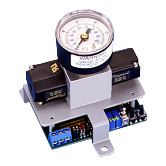
Electropneumatic Transducer
IP-411 and IP-413
SPECIFICATIONS
*
±
Accuracy
:
1%
FS
Maximum Supply Pressure: 40
PSIG
Pressure Differential: 0.1
(supply to branch)
PSIG
Supply Voltage: 18 to 28
or
VAC
VDC
Supply Current: 150
A
M
Enclosure: 18 Ga. C.R. steel chassis
Finish: Baked on enamel PMS2GR88B
Conformance:
EMC
standards
EN55014(1993)/EN60730-1(1992)
Compensated Temperature Range: 25°
65°
)
C
±
T. C. Error:
0.025%/°
(.03%/°
)
F
C
Media Compatibility: Clean dry air or any inert gas
Port Connection: ¼-inch O.D. poly tubing
Environmental: 10 to 90%
non-condensing
RH
Termination: Screw terminal block
Wire Size: 12 Ga. maximum
Input Impedance: 301 ohms (4 - 20
(0 - 5 or 0 - 10
)
VDC
Weight: 1.0 lb. (.45 kg)
*
Includes nonlinearity, hysteresis, and non-repeatability.
INSTALLATION PRECAUTIONS
Do not use on an oxygen service, in an explosive or
hazardous environment, or with flammable or combustible
material.
Disconnect the power supply before installing the transducer.
Failure to do so can result in electrical shock and equipment
damage.
Make all connections in accordance with the job wiring
diagram and national and local electrical codes. Use only
copper conductors.
Use electrostatic discharge precautions such as wrist straps
when installing and wiring the transducer.
Do not exceed ratings for the transducer.
This transducer contains a half-wave rectifier power supply
and must not be powered from transformers powering other
devices with non-isolated full-wave rectifier power supplies.
Verify that the main supply pressure does not exceed 40
Ensure a minimum of 6 to 10 feet (1.8 to 3.0 m) of tubing
between the transducer and the actuator.
For a 24
supply voltage, make sure that the hot and
VAC
neutral are not reversed. If more than one transducer is being
powered from the same transformer, the hot and neutral
should be the same for each transducer.
MOUNTING
The electropneumatic transducer must be mounted in an
upright position so that the main and branch ports face
upwards and the gauge can be read easily.
1. Select the mounting location.
2. Mount the transducer on a vertical surface with three
#8 self-tapping screws (not provided).
M2073/0303
3. Pull wires through the bottom of the transducer and
make the necessary connections.
4. Make the pneumatic connections.
WIRING
Use maximum 12
¼-inch O.D. poly tubing for main and branch pneumatic
connections. The electropneumatic transducer can be
powered with a 18 to 28
1. Connect the power supply voltage wire to the supply
[+] terminal and the power supply common to the
common [-] terminal.
2. Connect the controller output wire to the input [I]
terminal and the controller common wire to the
common [-] terminal.
EN50082-1(1992),
to 150°
(4°
to
F
F
C
); 10K ohms
A
M
JUMPER CONFIGURATIONS
Jumper configuration varies by output type:
.
PSIG
CHECKOUT
To verify proper operation of the transducer, adjust the input
signal to obtain a maximum output pressure for the
appropriate range. The output should be 15 or 20
adjust the input signal to obtain a minimum output pressure.
The output should be 0 or 3
wire for wiring terminals and flexible
AWG
or
supply.
VAC
VDC
or
.
A
VDC
M
. Next,
PSIG
.
PSIG
CALIBRATION
All electropneumatic transducers are factory calibrated to
meet or exceed published specifications. If field adjustment is
necessary, follow these instructions:
1. Connect air to the Main port.
2. Connect an accurate gauge to the Branch port using a
minimum of 6 to 10 feet (1.8 to 3.0 m) of tubing.
3. Connect an 18 to 28 VAC or VDC power source to the
[+] and [-] terminals. The maximum supply voltage
should not exceed 30
/
.
VAC
VDC
4. Apply a low input signal to the [-] and [I] terminals (0
or 4
).
VDC
A
M
5. Adjust [Z] to obtain the desired low output pressure.
6. Apply a high input signal to the [-] and [I] terminals (5/
10
or 20
).
VDC
A
M
7. Adjust [S] to obtain the desired high output pressure.
8. Repeat steps 4 through 7 until the transducer is fully
calibrated.
DIMENSIONS
Advertisement

Related Manuals for Omega IP-411

Summary of Contents for Omega IP-411
- Page 1 Electropneumatic Transducer IP-411 and IP-413 M2073/0303 3. Pull wires through the bottom of the transducer and CALIBRATION make the necessary connections. SPECIFICATIONS All electropneumatic transducers are factory calibrated to 4. Make the pneumatic connections. meet or exceed published specifications. If field adjustment is ±...
- Page 2 Manual REVISION...
- Page 3 In no event shall OMEGA be liable for consequential, incidental or special damages. CONDITIONS: Equipment sold by OMEGA is not intended to be used, nor shall it be used: (1) as a “Basic Component” under 10 CFR 21 (NRC), used in or with any nuclear installation or activity;...