Advertisement
Quick Links
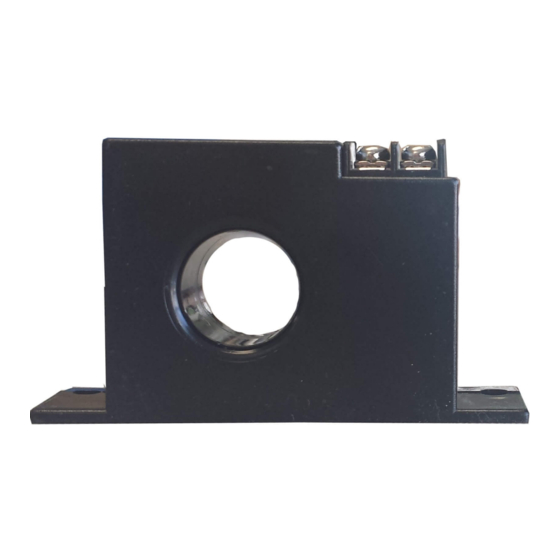
Amp Sensors
MODEL
AS-0 | AS-5 | AS-10 | AS-15
1. The high current switch / dryer fan control is a solid-state N.O. high current AC switch that operates a dryer booster fan directly
2. This device senses when a clothes dryer is drawing ~1 Amp of current and then closes the output switch to activate the dryer vent booster fan
3. When the dryer cycle is complete and the current drops below the threshold, the output switch will remain closed for a set time (see Time Delay in the
specification sheet's specifications section) to allow heat to be removed from the vent before the switch is opened again
4. The device requires no field adjustments and only two wire connections for easy installation
5. It is designed to mount in a standard electrical box and the dryer supply wire passes through the centre of the sensor so no physical connection is made
6. The device output will switch loads at 120V AC and 2.5 Amps maximum. Internal circuits are totally powered by induction from the line being monitored
CAUTION
PLEASE READ INSTRUCTION BEFORE COMMENCING INSTALLATION AND RETAIN FOR FUTURE REFERENCES.
Electrical products can cause death or injury, or damage to property.
If in any doubt about the installation or use of this product, consult a competent electrician.
INSTALLATION GUIDE
3-Phase Wiring
1. Disconnect and lock-out all power sources during installation
2. Mount sensor in a convenient location, within or adjacent to the breaker panel. Alternatively, the sensor can be installed
inside the dryer electrical compartment. (Refer to Installation Drawings on the next page of this instruction manual)
3. (3-Phase systems) Disconnect and loop the neutral power wire, WHITE, through the current sensor and reconnect
4. (220V AC 3-wire single-phase systems) Determine which of the Hot wires is active for the dryer only (This is necessary for
stacked washer/dryer units). Verify that there is sufficient current to trip the current switch (minimum of 1 amp).
If required, the wire can be looped through twice to increase the current read by the switch
5. Connect the fan power supply, as shown 120V AC max, to the top terminals of the current sensor
info@ortechindustries.com
www.ortechindustries.com
WARNING
WARNING — THE INSTALLATION MUST BE CARRIED OUT BY A QUALIFIED ELECTRICIAN.
1. Disconnect and lock-out all power sources during installation as severe injury or death can result
from electrical shock due to contact with high voltage conductors
2. Never rely on status indicating devices only to determine if power is present in a conductor
3. Ensure all installations are in compliance with applicable electrical codes and that the installation is
completed by qualified installers familiar with the standards and proper safety procedures for high
voltage installation
Application Notice
13376 Comber Way
Surrey BC V3W 5V9
375 Admiral Blvd
Mississauga
,
ON L5T 2N1
Instruction Manual
1-888-543-6473
1-888-541-6474
Advertisement

Summary of Contents for Ortech AS-0
- Page 1 Amp Sensors Instruction Manual MODEL AS-0 | AS-5 | AS-10 | AS-15 WARNING WARNING — THE INSTALLATION MUST BE CARRIED OUT BY A QUALIFIED ELECTRICIAN. 1. Disconnect and lock-out all power sources during installation as severe injury or death can result from electrical shock due to contact with high voltage conductors 2.
- Page 2 Amp Sensors Instruction Manual MODEL AS-0 | AS-5 | AS-10 | AS-15 INSTALLATION DRAWINGS Installation at Dryer Junction Box (3-Phase) Neutral / White Power to Dryer 120V AC Dryer Junction Box Current Sensor Installation at Dryer Junction Box (3-Wire Single Phase)