Advertisement
Quick Links
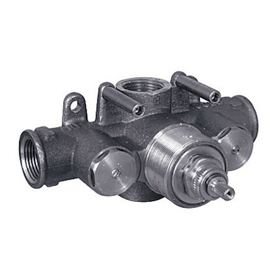
SS-TH1000 ½" THERMOSTATIC VALVE
SS-TH2000 ½" THERMOSTATIC VALVE WITH
BUILT IN VOLUME CONTROL
Features:
Ability to pre-select water temperature – thus conserving water
Compensates for water pressure fluctuations preventing scalding
Safety button at 100°F prevents accidental scalding
High flow rates allow for multiple shower applications
Listed by IAPMO, CSA, NSF, and other municipalities
Specifications:
o Operating pressure is 20 PSI to 72 PSI
o When pressure is higher than 72 PSI a pressure reducer (fitted before the valve) is required.
o Temperature range is 50°F to 180°F
o Recommended setting is 29 PSI and 149°F
Note:
DO NOT USE PLUMBER'S PUTTY ON ANY OF THE BRASS COMPONENTS
This will cause the finish to tarnish and void the warranty. A non-corrosive Alkoxy Silicone is
recommended.
DURING SWEATING OF LINES DO NOT OVERHEAT CASTING
Overheating may cause damage to internal mechanism and void the manufacturer's warranty as
well as increase the risk of scalding.
COPPER ADAPTORS MAY BE REQUIRED TO COMPLETE YOUR INSTALLATION
Shipping weight: 4 lb (SS-TH1000/3000) or 5 lb (SS-TH2000/4000)
Shipping dimension: 7"x7"x3.5" (SS-TH1000/3000) or 8"x7.5"x6" (SS-TH2000/4000)
Note:
Separate wall stops/shut off valves/volume controls (SS-TS150 or SS-TS200) may be needed in
conjunction with this valve. A thermostatic valve's only function is to mix temperature.
SS-TH3000 ¾" THERMOSTATIC VALVE
SS-TH4000 ¾" THERMOSTATIC VALVE WITH
Diagram 1: Flow Rate Vs. Pressure
INSTALLTION FOR
THERMOSTATIC VALVES
BUILT IN VOLUME CONTROL
Rev. 10/17
P a g e
| 1
Advertisement

Related Manuals for Watermark SS-TH1000


Summary of Contents for Watermark SS-TH1000
- Page 1 Overheating may cause damage to internal mechanism and void the manufacturer’s warranty as well as increase the risk of scalding. COPPER ADAPTORS MAY BE REQUIRED TO COMPLETE YOUR INSTALLATION Shipping weight: 4 lb (SS-TH1000/3000) or 5 lb (SS-TH2000/4000) Shipping dimension: 7”x7”x3.5” (SS-TH1000/3000) or 8”x7.5”x6” (SS-TH2000/4000) Note: ...
-
Page 2: Valve Installation
INSTALLTION FOR THERMOSTATIC VALVES Valve Installation 1. Flush the lines of all dirt and debris. Failure to completely flush the lines will cause valve failure and will void the manufacturer’s warranty. 2. Fit the valve on the wall without removing the plastic cover on the control spindle. Turning the control spindle will change the temperature setting which is pre-calibrated at the factory. - Page 3 THERMOSTATIC VALVES Diagram 3 Diagram 4: Representative Trim SS-TH1000 or SS-TH3000 SS-TH2000 or SS-TH4000 Parts Checklist – SS-TH1000 or SS-TH3000 (SS-TH2000 or SS-TH4000) Carefully remove all parts from the box. The following parts should be included. Item # Description Qty.
-
Page 4: Temperature Setting
NOTE: To prevent the handle from accumulating mineral build up which can cause the handle to “lock up,” the handle must be turned on an occasional basis. Diagram 6: Cartridge Removal/Check Valve Removal Parts List SS-TH1000 or SS-TH3000 (SS-TH2000 or SS-TH4000) Item # Description Qty. - Page 5 Repair or replace cartridge in wall stop/ volume control volume control Valve body too deep into wall The measured rough in or Install an extension kit: finished wall surface is incorrect SS-EXT41 for SS-TH1000 or SS-TH3000 SS-EXT51 for SS-TH2000 or SS-TH4000 P a g e...
- Page 6 INSTALLTION FOR THERMOSTATIC VALVES Diagram 7 – Dimensional Drawings Diagram 8: Sample Layouts Thermostatic Valves P a g e...