Advertisement
Quick Links
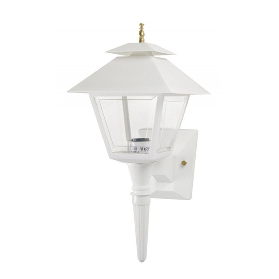
MODELS: 105, 106
DO NOT CALL OR RETURN TO THE RETAILER. Call for direct assistance at 1-877-870-9283.
PLEASE READ ALL INSTRUCTIONS CAREFULLY BEFORE INSTALLING FIXTURES.
BEFORE INSTALLATION
1. Please check to see that your fixture was not damaged during shipment, and that you received all the hardware needed for
installation. While we strive for perfection, accidents do happen. If you have a problem or are missing any parts, please call
us at 1-877-870-9283 immediately.
2. CAUTION: Disconnect main power at the breaker box before beginning installation. Do not turn power off at the wall
switch only. Failure to properly disconnect the main power supply may result in serious injury.
3. CAUTION: Install the appropriate size lamp in your Stone fixture. Do not exceed the manufacturer's maximum wattage
restrictions.
4. SPECIAL NOTE: For easier installation, it is recommended the two (2) people be used when making the electrical connections
and mounting the fixture.
COACH-LITE PARTS LIST
1 - Lantern cage with canopy attached and wall mounting unit assembled to lantern cage
1 - Spindle
1 - 4" x 4" Top Cap
1 - Package containing (4) lens panels
1 - Bag containing:
1 - Decorative Finial
1 - Finial Lock Washer
1 - Universal Mounting Plate
FINIAL ASSEMBLY
1. Push the finial screw up through the hole in the larger canopy.
2. Place the lock washer over the finial screw.
3. Next, place the smaller size 4" x 4" cap over the finial screw and lock washer.
4. Run the finial onto the finial screw. NOTE: Be certain to rap the finial several times with the hole down to
remove and chips that may still be lodged in the threaded portion.
5. Tighten the assembly by turning in a clockwise direction.
PANEL INSERTING INSTRUCTIONS
1. The raised beveled portion of the panels face the outside of the lantern cage.
2. The smaller end of the panel is inserted into one of the four slots located on the inside and bottom portion
of the lantern cage.
3. Continue inserting lenses in a counterclockwise direction from the first. Apply downward pressure to the
fourth panel to snap it into position.
4. Apply downward pressure at all four corners where the panels meet to properly align them.
MOUNTING INSTRUCTIONS
1. Connect lead wires from lantern to incoming lines. Mount universal mounting bar to splice box. Insert two
thumb screws through back plate holes and screw into universal mounting bar.
2. Push spindle onto wall bracket base. (See Figure A)
NOTE: If the spindle does not push easily or completely into the base of the lantern, add several drops of any
household lubricant to the inside lid of the spindle.
Customer Service 1-877-870-9283
1103004GUES Rev. B
INSTALLATION GUIDE
If for some reason you are missing parts of have a problem with your fixture
1 - Finial Screw
2 - #8/32 x 1" Thumb Screws
1 - Green Ground Clip
FIGURE A
www.wavelighting.com
ALWAYS CONNECT BLACK TO BLACK, WHITE TO WHITE,
AND BARE OR GREEN GROUNDING CONNECTORS
Advertisement

Related Manuals for WAVE LIGHTING 105

Summary of Contents for WAVE LIGHTING 105
- Page 1 INSTALLATION GUIDE MODELS: 105, 106 If for some reason you are missing parts of have a problem with your fixture DO NOT CALL OR RETURN TO THE RETAILER. Call for direct assistance at 1-877-870-9283. PLEASE READ ALL INSTRUCTIONS CAREFULLY BEFORE INSTALLING FIXTURES.
- Page 2 Clean only with mild soap and water. Avoid spraying with Cleansers, Mark means lamp contains Mercury. Follow disposal laws. Insecticides, and Pesticides that a petroleum based hydrocarbon See www.lamprecycle.org products. These will degrade Luminaire. COLD WEATHER STARTING INFORMATION: For temperatures below 0˚F, leave the lamp on continuously - starting with warm lamps.