Advertisement
Quick Links
1) INTRODUCTION
This instruction is a guide for general installation,
operation, maintenance and storage for J Flow
Controls pneumatic diaphragm actuators. Please
follow instructions to ensure optimum performance
and Safety.
2) IMPORTANT SAFETY PROCEDURES
JFD series actuators shall only be used as actuators
on valves or damper application. Levers, racks and
similar cannot be used to transmit movement without
protective equipment.
ALWAYS DISCONNECT AIR LINES AND
ELECTRICAL SOURCES PRIOR TO
PERFORMING MAINTENANCE ON THE
ACTUATOR
Relieve trapped medium pressure within ball
valve or plug valve body cavities before
removing the actuator from valve assemblies
for maintenance.
3) OPERATING MEDIUM, PRESSURE AND
TEMPERATURE
Operating medium:
Use air, gas, oil, and water.
Operating pressure
Do not exceed 100 PSI (7 bar)
4) LUBRICATION
Use standard seals and grease, the operating
temperature range is -4 (-20 ) to
+150 (+65C ).
For operating medium, pressure and temperature
outside these ranges, please
consult J Flow Controls.
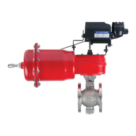
OPERATION AND INSTRUCTION MANUAL
Spring Return Diaphragm pneumatic actuator
JFD Series
5) OPERATING PRINCIPLE
Air (or Medium supplied) to the Diaphragm
(17) casing pushes the actuator stem
downward. This action compresses the
spring, which in turn pushes the actuator
shaft (12) back up when the supply pressure
is decreased or lost.
The spring shaft (12) trurns the drive stem (3)
90 degrees and creates a rotary motion.
6) ACTUATOR STROKE ADJUSTMENT
Travel Stops and Settings
Travel Stop and settings. Actuator with 90°
rotation, the stroke adjustment is +/- 4°
Upper and Lower Adjusting screws to set
open and closed stops.
J Flow Controls, LLC
14 De Camp
Cincinnati, OH 45216
Phone: 513-731-2900
Fax 513-731-6939
Advertisement

Related Manuals for Jflow controls JFD Series


Summary of Contents for Jflow controls JFD Series
- Page 1 The spring shaft (12) trurns the drive stem (3) 90 degrees and creates a rotary motion. JFD series actuators shall only be used as actuators on valves or damper application. Levers, racks and similar cannot be used to transmit movement without protective equipment.
- Page 2 7) ACTUATOR DISASSEMBLY Remove actuator from the valve and valve mounting bracket (if needed). EXTREME CAUTION SHOULD BE USED WHEN DISASSEMBLING SPRING DISASSEMBLY SHOULD NOT BE ATTEMPTED. THE SPRING ASSEMBLY IS UNDER TENSION AND COULD POSE A DANGER TO PERSONNEL. It is recommeneded that the Spring assembly be removed by J Flow Controls, LLC.
- Page 3 JFD ACTUATOR EXPLODED VIEW NAME OF PARTS MATERIALS NAME OF PARTS MATERIALS DRIVE BODY DUCTILE DIAPHRAGM RUBER DRIVE CAP ANSI 1010 DRIVE STEM DUCTILE BOLTS BEARING -TFE- SPRING BRACKET DUCTILE THRUST WASHER DIAPHRAGM COVER ANSI 1010 BODY BOLTS SS 304 CARBON STEEL DRIVE PIN ANSI 4135 ADJUST BOLT CARBON STEEL ADAPTER ANSI 1045 BEARING ADAPTER CARBON STEEL BOLTS BOLT SS 304 SPRING (BASE) ANSI 1010 BOLT SS 304...
- Page 4 8) Clockwise and Counter-Clockwise Rotation Set Up Cast Side Cover Side Clockwise Rotation Counter - Clockwise Rotation Counter- Clockwise on Fail Clockwise on Fail 9) Storage To preserve the actuator, ensure the plastic caps are installed to prevent dust and other debris from entering the actuator. Ensure the Drive is covered with plastic or the unit is boxed.