Advertisement
Quick Links
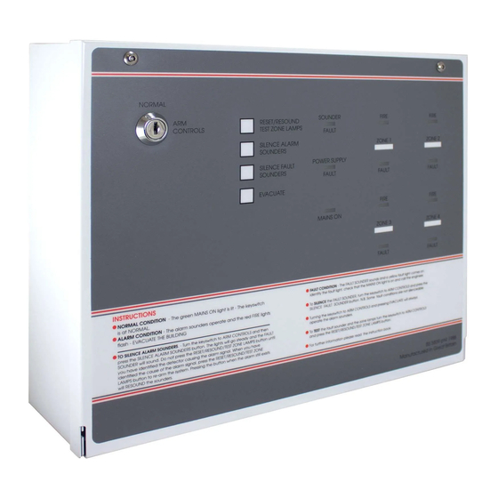
FP4E
4 Zone Economy Fire larm Control Panel
Installation Instructions
THIS EQUIPMENT MUST ONLY BE INSTALLED AND MAINTAINED BY A SUITABLY SKILLED AND TECHNICALLY
COMPETENT PERSON. THIS EQUIPMENT IS A PIECE OF CLASS 1 EQUIPMENT AND MUST BE EARTHED.
DO NOT CHANGE ANY PANEL CONNECTIONS WITH THE PANEL'S POWER APPLIED (MAINS OR BATTERY POWER).
INST LL TION PROCEDURE
All cables must be installed in accordance with all applicable national, regional or local standards. In the UK this is BS 7671 IEE
Wiring Regulations and BS 5839-1, Fire detection and alarm systems for buildings: Code of practice for system design, installation
and maintenance. Fire resistant, screened cable should be used throughout the installation and Mains wiring should be
segregated from extra low voltage field wiring.
For PERMANENTLY CONNECTED equipment, a readily accessible disconnect device shall
be incorporated external to the equipment.
The general requirement for the Mains supply to the panel is fixed wiring, using 3 core
2
cable, (no less than 1mm
and no more than 2.5mm
system fed from an isolating switched fused spur, fused at 3A. The Mains supply must
be exclusive to the panel.
HINT. As an alternative to a switched
fused spur, a double pole isolating
device (B) may be used in the Mains
feed from the Main Distribution
Board (A) to the panel (C), providing
it meets the appropriate wiring
regulations – see Fig 1.
•
Remove the panel's lid (disconnect attached loom connector).
•
Fit the panel's back box securely to a wall using the mounting holes provided and
suitable screw fixings. Remove required number of knockouts and fill holes with good
quality cable glands – see Fig 2.
•
Gland field cables and terminate all screens to the panel.
CAUTION: DO NOT use an insulation tester (Megger) with any electronic devices
connected as the test voltage will totally destroy the devices.
•
Test field cables and ensure they are fault-free, i.e. check continuity of cable runs
(including screens).
•
Connect external Mains cable to the panel's fused Mains terminal block (with Mains
isolated) – see Fig 2.
CAUTION: RISK OF EXPLOSION IF BATTERY IS REPLACED BY AN INCORRECT TYPE.
DISPOSE OF USED BATTERIES ACCORDING TO THE INSTRUCTIONS.
Also, if the battery leads are connected in reverse, the battery fuse (F1) will blow
which may damage the panel and invalidate the warranty.
•
Position and connect the panel's two internal 12V sealed lead acid batteries (with
battery supply isolated) – see Fig 3 & Fig 4.
•
Connect zone circuits to the panel – see Fig 5.
•
Connect sounder circuits to the panel – see Fig 5.
•
Connect ancillary connections to the panel.
•
Refit the panel's lid (re-connect loom connector).
•
Apply Mains and battery supply to power up the panel.
•
The panel should be in normal mode. If not, investigate and rectify any faults
indicated on the panel.
•
Finally, test the panel – see pages 2 & 3.
TYPICAL ZONE CIRCUIT - Call points wired before detectors
- Detector base diodes not needed.
CALL POINT
-
CPR
+
CIRCUIT NOT MONITORED!
TYPICAL ZONE CIRCUIT - With mixed order call points and detectors
- Detector bases fitted with continuity diodes and negative connection linked out.
CALL POINT
+
CPR
-
-
+
FIRE ALARM
ncill ries
2
), or a suitable three conductor
A
CALL POINT
DETECTOR
DETECTOR
CPR
DO NOT SPUR -
DETECTOR
DETECTOR
CALL POINT
CPR
ELECTRONIC MONITORING UNIT (EMU)
EMU PANEL MODULE
Approved Document No. DFU0384011 Rev 2 Draft 4
Fig 1
3A
B
≥
1.0mm
2
< 2.5mm
2
Fig 5
TYPICAL SOUNDER CIRCUITS
Only use polarised sounders!
EOLR
5
Remove EOLR from
terminal block and
6
fit to last detector.
7
8
BF378 or
BF378M
EOLR = End of Line Resistor (6k8Ω, 0.25W) - supplied
CPR = Call Point Resistor (470 - 680Ω, 0.5W) - supplied with call point
(Part No. FF384-3)
B
B
A
B
Power Rating
Mains cable
A
C
L(LIVE), N(NEUTRAL),
B
A = Mounting Holes, B = Cable Knockouts
space for batteries
(bottom of back box)
+
12V Battery
–
Black
Connections
Wire
to Panel
(supplied)
Red
Wire
Black
Wire
DO NOT SPUR -
CIRCUIT NOT MONITORED!
-
+
+
+
SOUNDERS
-
+
+
+
SOUNDERS
+
+
Fig 2
B
B
B
B
B
B
B
B
A
A
(EARTH)
Fig 3
Fig 4
Shorting Link
(supplied)
–
12V Battery
Red
Wire
(supplied)
OR
12V Battery
+
–
12V Battery
EOLR
Remove EOLR from
terminal block(s) and
fit to last sounder.
EOLR
DO NOT make off
more than 2 circuits
in the panel
1 of 4
Advertisement

Related Manuals for C-TEC FP4E

Summary of Contents for C-TEC FP4E
- Page 1 FP4E 4 Zone Economy Fire larm Control Panel (Part No. FF384-3) Installation Instructions THIS EQUIPMENT MUST ONLY BE INSTALLED AND MAINTAINED BY A SUITABLY SKILLED AND TECHNICALLY COMPETENT PERSON. THIS EQUIPMENT IS A PIECE OF CLASS 1 EQUIPMENT AND MUST BE EARTHED.
- Page 2 TESTING THE P NEL When testing the panel with the panel lid open, always isolate the Mains and disconnect the batteries. The panel can be tested before connecting field wiring. If testing before installation, ensure the end-of-line resistors are fitted in the panel’s sounder and detector terminal blocks. Position and connect two suitable 12V batteries in the panel as shown in Fig 3 and Fig 4 (page 1).
- Page 3 FIRE CONDITION Simulate a Fire condition by connecting and activating a Call Point, or by fitting a 470 to 680Ω resistor across terminals 9 & 10. The sounder output relay will operate. The ZONE 1 FIRE indicator lights and warning beeper sounds. Press SILENCE ALARM SOUNDERS.
- Page 4 INTERNAL (3) Connection to Landlord’s Panel. ZONE ISOLATED ENGINEER TEST SELECTED Engineer Detector Test Zone Isolate FP4E (0.8A SUPPLY) Revert to short circuit = fire (no resistors in Call Points) Part No. FF384-3 POWER SPECIFICATION POWER SPECIFICATION MAINS SUPPLY VOLTAGE...