
Summary of Contents for Tech Works ICM-8C
- Page 1 ICM-8C, 16C, 24C, and 32C Intercom Control Master 8-32 Stations with All Page and Scan OPERATION AND INSTALLATION MANUAL 800-813-1080 www.techworks-usa.com 07/20...
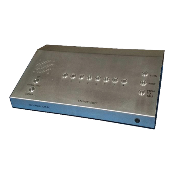
- Page 2 Introduction: The ICM-8, 16, 24, & 32C are complete Intercom Control Master, ruggedized for use in harsh environments such as correctional facilities while providing high quality audio communication with complete control. The ICM-*C was designed to withstand physical attacks and deliberate abuse designed to disable the unit.
- Page 3 Answering a call: 1. When the call-in button is depressed on a remote station, the ICM panel will beep and the call- in LED on the ICM will flash to show the station that placed the call. 2. Pressing the station selector button with the flashing LED selects the station to take the call. You are now listening to the remote location.
-
Page 4: Setup And Configuration
Installation Instructions for ICM-xC Intercom Control Panel SET UP AND CONFIGURATION – The ICM intercom comes complete and ready to use. Station selection can be “Press and Hold” operation or a “Latching” press and release operation. To change these configurations simply remove the top cover by removing the screws. - Page 5 The ICM-xC has Station Scanning and Zone Paging available. Both functions are programmable. You can set which stations are scanned and how long the channel is “Held” for listening. The time the audio channel is held on during scanning is set by the Scan Dwell. You can set which stations are included in a “Scan“, and also what stations are included in a “Page”...
- Page 6 Connections Field wiring connections: Station wires are connected to the ICM via 66 style punch block connections: STATION-1 SPEAKER + STATION-1 SPEAKER - CALL-IN (–) (SHIELD / COMMON) STATION-1 CALL-IN + STATION-1 LED – (FLASH) LED (+) (24VDC) STATION-2 SPEAKER + STATION-2 SPEAKER - CALL-IN (–) (SHIELD / COMMON) STATION-2 CALL-IN +...
- Page 7 Station Wiring Connection – A 25 pair cable is provided for connecting up to 8 stations to the ICM. Connections are made to existing field wiring according to the following connection diagram. COLOR FUNCTION BLUE–WHITE STATION-1 SPEAKER + WHITE-BLUE STATION-1 SPEAKER - ORANGE-WHITE STATION-1 CALL-IN - WHITE ORANGE...
-
Page 8: Power Connection
Power Connection – THIS UNIT OPERATES ON 24VDC. DO NOT CONNECT 120VAC DIRECTLY TO ICM. CONNECTING 120VAC POWER TO UNIT WILL BURN UP POWER SUPPLY AND CIRCUIT BOARDS AND VOID THE WARRANTY. 1. Connect provided 3 conductor power cable to 24 VDC power supply. The power supply should produce a minimum of 3.5 amps of power.