Advertisement
Quick Links
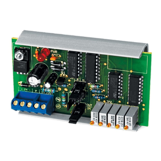
ANALOG RESCALING MODULE
INTERFACE SERIES
Installation & Operation Instructions
ARM
GENERAL INFORMATION
The ARM is an analog rescaling module which
accepts an analog (voltage or current) input signal
and rescales it to another voltage or current output
signal. The top-adjust trimmer potentiometers can
be used to make ne adjustments to output ranges
for maximum exibility. This device can attenuate
an input signal to 100%. The ARM also has an
adjustable gain and o set. The output gain can be
adjusted from 1 to 25 times the input (gain will vary
depending on input). The o set of the output can
be adjusted anywhere from 0 to +/- 20 VDC. The
ARM also has the ability to reverse an input signal.
The ARM has a regulated 20 VDC power supply
output to power sensors. The ARM can also accept
a resistance input by using voltage divider
applications. The ARM is
however, factory calibration is available upon
request for an additional charge. This will speed up
installation time for the end user.
MOUNTING INSTRUCTIONS
Circuit board may be mounted in any position. If circuit board slides out of snap track, a nonconductive
"stop"
may be required. Use only ngers to remove board from snap track. Slide out of snap track or push against
side of snap track and lift that side of the circuit board to remove. Do not ex board or use tools.
WIRING INSTRUCTIONS
PRECAUTIONS
• Remove power before wiring. Never connect or disconnect wiring with power applied.
•
When using a shielded cable, ground the shield only at the controller end. Grounding both
ends can cause a ground loop.
• It is recommended you use an isolated UL-listed class 2 transformer when powering the unit
with 24 VAC. Failure to wire the devices with the correct polarity when sharing transformers may
result in damage to any device powered by the shared transformer.
• If the 24 VDC or 24VAC power is shared with devices that have coils such as relays, solenoids,
or other inductors, each coil must have an MOV, DC/AC Transorb, Transient Voltage Suppressor
(ACI Part: 142583), or diode placed across the coil or inductor. The cathode, or banded side of the
DC Transorb or diode, connects to the positive side of the power supply. Without these snubbers,
coils produce very large voltage spikes when de-energizing that can cause malfunction or
destruction of electronic circuits.
• All wiring must comply with all local and National Electric Codes.
Automation Components, Inc.
2305 Pleasant View Road | Middleton, WI 53562
Phone: 1-888-967-5224 | Website: workaci.com
eld calibratable,
Page 1
FIGURE 1: DIMENSIONS
BOARD
3.69"
2.17"
(55.27mm)
SNAP TRACK
2.30"
58.42mm)
2.70"
(68.58mm)
Phone: 1-888-967-5224
Website: workaci.com
(93.82mm)
0.70"
(17.78mm)
Version: 3.0
I0000470
Advertisement

Related Manuals for aci ANALOG RESCALING Series


Summary of Contents for aci ANALOG RESCALING Series
- Page 1 MOV, DC/AC Transorb, Transient Voltage Suppressor (ACI Part: 142583), or diode placed across the coil or inductor. The cathode, or banded side of the DC Transorb or diode, connects to the positive side of the power supply. Without these snubbers, coils produce very large voltage spikes when de-energizing that can cause malfunction or destruction of electronic circuits.
-
Page 2: Factory Calibration
FIGURE 2: WIRING OFFSET + 24 - O - + FINE GAIN OSET REV ATTN 24 VAC/DC Analog Output Signal Power Supply Analog Input Signal Input from 2-wire mA loop powered sensor (using 20V ARM "P" terminal 20 VDC Note: 20VDC Regulated Accessory Power output used for power) at this for resistance to analog conversions... - Page 3 EQUIVALENT CALIBRATION VOLTAGE (Continued) Equivalent Calibration Voltage = Required Input Signal Amps x 250 Example: 1 VDC is the equivalent calibration voltage for a 4 milliamp input signal (1 = .004 x 250) or 5 VDC is the equivalent calibration voltage for a 20 milliamp input signal (5 = .020 x 250).
- Page 4 EQUIVALENT CALIBRATION VOLTAGE (Continued) To calculate the voltage input signal span, subtract the minimum voltage input signal from the maximum input signal (i.e. a 0 to 5 volt input signal will give you a 5 volt input signal span: 5-0=5). To calculate the voltage output signal span, subtract the minimum voltage output signal from the maximum voltage output signal (i.e.
- Page 5 ARM CALIBRATION WORK SHEET : Fill in and circle answers. 1. Input: minimum______maximum______ mA or VDC, Output: minimum______maximum______ mA or 2. Is the input VDC? Yes/No. Is the output VDC? Yes/No a) If yes to both, set jumper J3 (IN/OUT) to E and skip to step 5. b) If no to both, set jumper J3 (IN/OUT) to I and skip to step 5.
- Page 6 12. Supply the “input minimum” signal or equivalent to the input. Adjust the o set trim pot until the output reads the same as “output minimum”. 13. Is signal reverse acting? If not skip to step 14. If yes, refer to following: a) Set J1 to R.
-
Page 7: Product Specifications
Agency Approvals: RoHS2, WEEE WARRANTY The ARM Series is covered by ACI’s Two (2) Year Limited Warranty, which is located in the front of ACI’S SENSORS & TRANSMITTERS CATALOG or can be found on ACI’s website: www.workaci.com. W.E.E.E. DIRECTIVE At the end of their useful life the packaging and product should be disposed of via a suitable recycling centre. - Page 8 Automation Components, Inc. 2305 Pleasant View Road Middleton, WI 53562 Phone: 1-888-967-5224 Website: workaci.com Page 8 Automation Components, Inc. Version: 3.0 2305 Pleasant View Road | Middleton, WI 53562 I0000470 Phone: 1-888-967-5224 | Website: workaci.com...