Advertisement
Quick Links
VSST Switch Box
INSTALLATION MANUAL
Thank you for purchasing the Patlite Manually Controlled Signal Tower for your application.
Please read these instructions carefully before installation, maintenance and repair. Store this
manual in a safe place for future reference. If you have any questions regarding this product,
please contact your PATLITE sales representative.
NOTICE FOR SAFE OPERATION
In order to prevent injury to the user and other personnel or damage to assets, note the
following:
The warning indications are divided into the following classes according to the degree
of danger or damage incurred when the warning is not taken into consideration and the
product is not correctly used.
Failure to follow these instructions may lead to death or serious
Warning
injury.
Failure to follow these instructions may lead from slight to
Caution
medium injury or lead to property damage or injury to others.
The following symbols explain the nature of the information to be observed.
Described action is strictly prohibited. It is not to be carried out under any
circumstances.
!
Described action is "enforced". It should be carried out by all means.
1. To operate this product safely, please observe the following:
Warning
Be sure to disconnect the power when wiring, mounting, exchanging,
or repairing the product. Failure to comply may result in damage of
the internal circuitry and the danger of electric shock due to short-
circuiting.
Request the installation and wiring to be accompanied by a
professional contractor. Failure to comply may result in electric
!
shock, fire or falling from high places.
When this product is used for security purposes, it should be
(Enforced)
inspected daily. In addition, it is recommended that other security
products be used together with this product in case the product
malfunctions.
After installing this product, be careful not to use this product to
climb onto a machine or to get anything snagged onto this product
while it is mounted on equipment, etc. Failure to comply may result
in falling off the machinery or product damage may occur.
Caution
Do not substitute any parts from other products or disassemble this
unit for any other purpose than to direct-mount the enclosure. It may
cause malfunction or failure.
This product operates on DC24V.
(Prohibited)
2. Model Number Configuration
VSST - LCE
5 02
No. of LED Stacks:
1 : 1 Tier
2 : 2 Tiers
Tower Series:
3 : 3 Tiers
LCE : 40mm Diameter
4 : 4 Tiers
LE : 50mm Diameter
5 : 5 Tiers
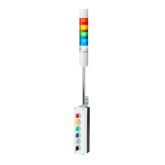
3. Part Names and Dimensions
Part Names
FB
P
- R Y G B C
LED Colors (Top-to-Bottom):
R : Red LED
P : Pole
Y : Amber LED
designator
G : Green LED
used in LE part
B : Blue LED
numbers only
C : Clear LED
Options:
Blank : Steady Illumination Only
FB : Steady/Flashing/ Alarms
NOTES:
1) Control box for 5-color, FB-style towers
shown
2) 5 and 6-switch boxes are the same size.
There is no alarm switch for 5-color
steady-only towers
3) Control boxes for 1-tier to 4-tier towers
will not have all the switches. Length of
the box will vary accordingly
-1-
Buy: www.ValinOnline.com | Phone: 844-385-3099 | Email: CustomerService@valin.com
Part Dimensions
1. VSST-LCE Series
W :
Box width
D1 :
Box depth
D2 :
Box + Switch depth
S :
Switch spacing
H :
Tower height
2. VSST-LE Series
W :
Box width
D1 :
Box depth
D2 :
Box + Switch depth
S :
Switch spacing
H :
Tower height
3. Installation
Caution
This product is for indoor use only (Do not use it outdoors).
Do not use this product in dusty places, or where water can get
inside.
When installing, ensure the mounting surface has sufficient strength
to hold the weight of the product. Also. Make sure there is no
vibration on the mounting surface. Otherwise, there is a risk of injury
(Prohibited)
or product damage in case the product should fall.
Bracket Mount
1. Refer to the Dimensions Section as needed to
facilitate mounting.
2. Be sure to match the correct data to the tower
that is being mounted.
3. Keep the assembly vertical as shown.
4. Make sure there is an AC outlet within reach
(1500mm) of the plug-in style power supply.
5. Prepare the mounting surface as required for
mounting the assembly.
6. Referring to the Bracket Mounting diagram, drill
the angle bracket mounting holes.
(mm)
7. Provide M8 screws or equivalent of the type and
length needed for this installation.
8. Install the bracket securely enough so the
assembly cannot be moved out of position.
(mm)
(mm)
-2-
Advertisement

Summary of Contents for Patlite VSST-LCE Series
- Page 1 INSTALLATION MANUAL 1. VSST-LCE Series Thank you for purchasing the Patlite Manually Controlled Signal Tower for your application. Please read these instructions carefully before installation, maintenance and repair. Store this manual in a safe place for future reference. If you have any questions regarding this product, Box width please contact your PATLITE sales representative.
- Page 2 (1) year from the initial date of shipment by PATLITE. In the even of a defect not caused by misuse or damage to the products, PATLITE will, at its option, repair, replace or return the purchase price for, defective products upon PATLITE's inspection.