Advertisement
Quick Links
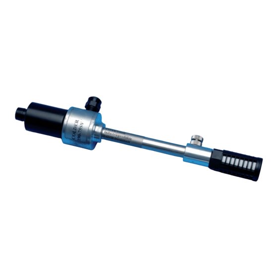
Operation Manual for „COLDER", Ultra-Cold Air Generator
Model No.
Working Air
Pressure
140-55 SV
3 – 7 kg/cm³
160-65 SV
3 – 7 kg/cm³
185-65 SV
3 – 7 kg/cm³
190-75 SV
3 – 7 kg/cm³
How to install a COLDER
1. Connect a compressed-air line with a COLDER. Prepare a nylon or urethane tube of
O. D. 8 mm x I.D. 5,5 mm (or bigger) for 190-75 SV / 185-65 SV and a tube of O.D. 6
mm x I. D. 4 mm (or bigger) for 160-65 SV/140-55 SV. Fit one end of the tube to the
connector of the COLDER firmly so that it will not come off. Fit the other end to
ensure by pulling the tube that they are fully connected.
The most suitable tube length is 2 m (or less) for 190-75 SV/185-65 SV and 1 m (or
less) for 160-65 SV/140-55 SV. If it is longer, COLDER may not perform properly
because the pressure of compressed-air supplied drops. When an air tubing is
connected with a COLDER, care is to be taken that couplings to be used should have
an inside diameter for the compressed-air passage of 5,5 mm minimum for 190-75
SV/185-65 SV and 4 mm minimum for 160-65 SV/140-55 SV. For connection of a
compressor and a dryer/filter, a bigger inside diameter is recommended.
2. Be sure to install a filter-separator on a compressed-air supply line.
3. If a dryer is not installed on the compressed-air line, a measure to prevent freezing
should be taken (See preventive measures against freezing given on the second page).
4. Install a COLDER in such a way that distance between the discharging outlet of cold
air and an object to be cooled is 20 mm to 30 mm and that the object is directly
exposed to cold air. If the distance is bigger, cold air required will not be obtained
because warmer ambient air will mix with the discharged cold air and the temperature
of cold air will rise.
Temperature Gage
Sensor Inserting
depth is about 50 mm
Cold Air Outlet
Compressed-air
Compressor
Consumption
Hp
45 – 85 l/min.
115 – 220 l/min.
180 – 420 l/min.
300 – 750 l/min.
Compressed Air
Tube Connector
190-75 SV, 185-65 SV, 160-65 SV, 140-55 SV
- 1 -
Connection Air Tube
O. D.
0,5 – 1 hp
6 mm
2 – 3 hp
6 mm
3 – 5 hp
8 mm
5 – 10 hp
8 mm
Control Knobs
Clockwise
+ Cold Air Temperature –
Airflow Fraction
Cold
Lock Nut
Eddy current
Warm Air Exhaust
I. D.
4,0 mm or over
4,0 mm or over
5,5 mm or over
5,5 mm or over
counterclockwise
Warm
Advertisement

Summary of Contents for Kager COLDER
- Page 1 I. D. 4 mm (or bigger) for 160-65 SV/140-55 SV. Fit one end of the tube to the connector of the COLDER firmly so that it will not come off. Fit the other end to ensure by pulling the tube that they are fully connected.
- Page 2 Turn the lock nut counter-clockwise and loosen it completely. Then turn the control knob clockwise to the bottom dead center tightly. Open the valve on the compressed-air line and let cold air flow into COLDER. At the same time check if the pressure gauge indicator is within working air pressure range given above.
- Page 3 2) When oil or grease is solidified inside, it can be washed out. Troubles. A COLDER has no working parts, which should bring you no trouble under normal operation. But, if it gives you any trouble due to manufacturing imperfection, please send it back to us without disassembling it.