Advertisement
Quick Links
Specifications
Coil Voltage . . . . . . . . . . . CSR-112 --- 12 Vdc 10%
Coil Current . . . . . . . . . . . CSR-112 --- 25 mA maximum
Relay Contacts . . . . . . . . . SPDT Form C (NO + NC)
Contact Rating . . . . . . . . . 5A @ 250Vac/30Vdc Resistive
Contact Resistance . . . . . . 30 m maximum
Operating Temperature . . . -15 to 60 C (5 to 140 F)
Operating Humidity . . . . . . 5 to 90 %RH, non-condensing
Terminal Block . . . . . . . . . 14 to 22 AWG
Dimensions . . . . . . . . . . . . 2 x 1.4 x 0.83 in
Enclosure Material . . . . . . ABS/PC, UL94 V-0
Manufacturing . . . . . . . . . . ISO 9001 Certified
Agency Approvals . . . . . . . cULus Listed
Operation
The CSR command relay attaches to the side of any full-
size CS type sensor or switch and adds a form C relay
function. It provides line voltage switching with control
either from an automation system digital output or from a
CS-610-200 or CS-GnG-200 current switch. A status LED
indicates the relay state and the relay output features both a
normally-open and a normally-closed contact.
The CSR/CS combination provides a convenient solution
when status indication and motor control are needed at a
single location. The CSR can accept a digital control signal
from the controller to activate the relay contacts which can
be used to provide power to the motor contactor to start the
motor. The CS switch will then provide a digital proof-of-
flow signal to the controller to indicate motor status.
Oct 13, 2009
www.greystoneenergy.com
CSR-124 --- 24 Vac/dc 10%
CSR-124 --- 13 mA maximum
2A @ 250Vac/30Vdc Inductive
(50.8 x 35.6 x 21.1 mm)
1-800-561-5611
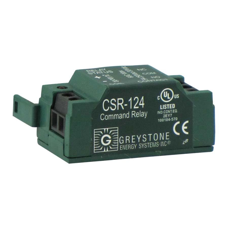
CSR-112 / CSR-124 Command Relay
WARNING
- Electric Shock Hazard, Use Caution
- Disconnect and lock out power before installation
- Follow national and local electrical codes
- Read and understand these instructions before installing
- Installation only by qualified electrical personnel
- Do not rely on this device to indicate line power
- Only install this device with CS current switch or sensor
- Do not use this device for life-safety applications
- Do not install in hazardous or classified locations
- Install this product in a suitable electrical enclosure
- Failure to follow these instructions will result in
death or serious injury.
Installation
- Read all warnings before beginning
- Ensure the selected device has the correct ratings
- Disconnect and lock out power
- Snap the CSR device onto the side of a CS product
- Mount the CS switch with two screws through the base or
snap onto a standard DIN mounting rail
- Place the monitored conductor through the sensor hole
- Wire the status output to the controller as shown in the
wiring diagrams (not polarity sensitive)
- Wire the coil input to the controller or status switch as
required
- Wire the relay contacts to the load as required
- Reconnect the power
support@greystoneenergy.com
Installation Guide
Page 1
Advertisement

Summary of Contents for Greystone CSR-112
- Page 1 - Ensure the selected device has the correct ratings - Disconnect and lock out power Coil Voltage ... CSR-112 --- 12 Vdc 10% - Snap the CSR device onto the side of a CS product CSR-124 --- 24 Vac/dc ...
- Page 2 CSR-112 / CSR-124 Command Relay Wiring The controller digital output (either 12 Vdc for CSR-112 or 24 Vdc for CSR-124) controls the CSR command relay coil input. When the coil signal is received, the CSR relay contacts close to supply 120 Vac power to the motor contactor.