Advertisement
Quick Links
LUXOMAT
Installation and Operating Instruction
1. Description
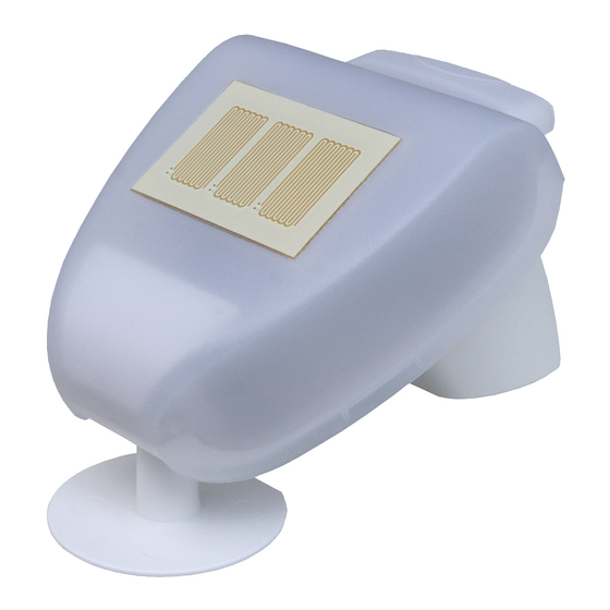
The Weatherstation KNX WTS-GPS measures temperature,
wind speed and brightness. It recognises precipitation and
receives a GPS signal for time and location. In addition, us-
ing location coordinates and the time, it calculates the exact
position of the sun (azimuth and elevation).
All values can be used for the control of threshold value-
dependent switching outputs. States can be linked via AND
logic gates and OR logic gates. The compact housing of
the KNX WTS-GPS includes the sensors, evaluation circuits
and buscoupling electronics.
2. Functions
• Brightness and position of the sun: The current light intensity
is measured by a sensor. In addition the KNX WTS-GPS
calculates the position of the sun (azimuth and elevation)
using time and location
• Shade control for up to 6 facades with slat and shadow
edge tracking
• Wind measurement: The wind strength measurement takes
place electronically and thus noiselessly and reliably, even
during hail, snow and sub-zero temperatures. Even turbulent
air and anabatic winds in the vicinity of the weather station
are recorded
• Precipitation recognition: The sensor surface is heated, so
that only drops and flakes are recognised as precipitation,
but not mist or dew. When the rain or snow stops, the sensor
is soon dry again and the precipitation warning ends
• Temperature measurement
• Weekly and calendar time switch: The weather station
receives the time and date from the integrated GPS receiver.
The weekly time switch switches up to 4 different periods per
day.
• With the calendar time switch up to 3 additional time periods
can be defined, in which up to 2 On/Off switches take
place. The switching outputs can be used as communications
objects. The switch times are set via parameters.
• Switching outputs for all measured and calculated values
(threshold values can be set via parameters or communica-
tions objects)
• 8 AND and 8 OR logic gates with each 4 inputs. All
switching events as well as 16 logic inputs (in the form of
communications objects) can be used as inputs for the logic
gates. The output of each gate can be optionally configured
as 1-bit or 2 x 8-bit
3. Installation and Commissioning
Installation, inspection, commissioning and trouble-
!
shooting of the device must only be carried out by a
competent electrician.
Disconnect all lines to be assembled, and take safety precau-
tions against accidental switch-on.
The device is exclusively intended for appropriate use. With
each inappropriate change or non-observance of the instruc-
tions for use, any warranty or guarantee claim will be void.
After unpacking the device, check immediately for any
mechanical damages. In case of transport damage, this must
immediately notified to the supplier.
KNX WTS-GPS
®
!
If damaged, the device must not be put into operation.
If an operation without risk may supposedly not be guaranteed,
the device must be put out of operation and be secured against
accidental operation.
The device must only be operated as stationary system, i.e.
only in a fitted state and after completion of all installation and
start-up works, and only in the environment intended for this
purpose.
B.E.G. Brück Electronic GmbH does not assume any liability
for changes in standards after publication of this instruction
manual.
4. Installation position
Choose an installation position in the building where wind,
rain and sun can be measured unhindered by the sensors. The
weather station must not be installed underneath any structural
parts from which water can still drip onto the rain sensor after
ithas stopped raining or snowing. The weather station must not
be shaded by anything,such as building structures or trees.
There must be at least 60 cm of free space underneath the
weather station to allow it to measure the wind correctly and to
prevent it from being snowed in when it snows. Please ensure
that extended awnings do not shade the device from sun and
wind.
Temperature measurements can also be affected by external
influences such as by warming or cooling of the building
structure on which the sensor is mounted, (sunlight, heating or
cold water pipes). Temperature variations from such sources of
interference must be corrected in the ETS in order to ensure the
specified accuracy of the sensor (temperature offset).
Magnetic fields, transmitters and interfering fields from
electricity consumers (e.g. fluorescent lamps, neon signs,
switched-mode power supplies etc.) can interfere with or even
cut out reception of the GPS signal.
Fig. 1
Wall
Wand
or
oder
Mast
pole
90°
min.
60 cm
The weather station must be mounted on a
vertical wall (or a pole).
Fig. 2
Horizontal
The weather station must be mounted in the horizontal
transverse direction (horizontally).
5. Attaching the mount
The weather station comes with a combination wall/pole
mount. The mount comes adhered by adhesive strips to the rear
side of the housing.
Fasten the holder vertically to the wall or pole.
Fig. 3
Collar
Steg
For wall mounting: Flat side to the wall,
crescent moon-shaped crosspiece facing up.
Fig. 4
Collar
Steg
For pole mounting: curved side to the pole,
crosspiece facing down.
6. Rear view and drill sketch
Fig. 5 a)
Ø 5 mm
22 mm
Langloch 7,5 x 5 mm
Oblong hole
Fig. 5 b)
14
22
71
35
28,75
Dimensions
Maße in mm
57,5
in mm
75
7. Preparing the weather station
Fig. 6
Unsnap cover
and remove
upwards
1 Lid with rain sensor
2 Lid notches
3 Housing lower section
The weather station lid with the rain sensor latches into place
on the lower edge to the right and left (see figure). Remove the
lid from the weather station. Proceed carefully to avoid tearing
off the cable connection between the circuit board in the lower
section and the rain sensor in the lid (cable with plug).
EN
1
2
3
Advertisement

Summary of Contents for B.E.G. LUXOMAT KNX WTS-GPS
- Page 1 Fig. 5 a) • Brightness and position of the sun: The current light intensity cut out reception of the GPS signal. is measured by a sensor. In addition the KNX WTS-GPS calculates the position of the sun (azimuth and elevation) Fig. 1 using time and location Ø...
- Page 2 As a precaution, the device should always be separated from power supply for maintenance works (e.g. deacti- vate or remove fuse). 1 2. Article / Part nr. / Accessory 90221 KNX WTS-GPS 13. Technical Data Housing: Housing UV- and shockresistant Polycarbonate...