Table of Contents
Advertisement
Quick Links
Specifi cations
External Power Supply
24VAC/DC (22-26V)
Power Consumption
<2VA Use class 2 power supply
Voltage Measurement
0-15, 25, 50, 150, 300 or 600 VDC
Monitored Line Impedance
>160K ohms
Output
+/-5 VDC
+/-10 VDC
Response Time
250 ms (10% to 90% value)
Accuracy
< 1% Full Scale
Output Impedance
>10K Ohms for stated accuracy
Isolation Voltage
2500 Volts
Frequency Range
DC only
Operating Temp.
-20°C to 50°C
(surrounding sensor)
Enclosure
UL94 V0 Rated
Environmental
-4 to 122 ° F
(-20 to 50° C),0–95% RH
Pollution Degree 2
Altitude to 2000 meters
Listings
Designed for UL/cUL, CE
For products intended for the EU market, the following is ap-
plicable to the CE compliance of the product:
The VTD-BD series are designed to comply with EN 61010-1
CAT III 600V max measurement category. Use 24 V input power
and fuse at 5 amps. Power source overvoltage category I as
defi ned per EN 61010-1
Warning! Risk of danger
Safe operation can only be guaranteed if the
transducer is used for the purpose for which is
was designed and within the limits of the techni-
cal specifi cations. When this symbol is used, it
means you must consult all documentation to
understand the nature of potential hazards and
the action required to avoid them.
Warning! Risk of electrical shock
When operating the transducer certain parts may
carry hazardous live voltage (e.g. primary con-
ductors, power supply). The transducer should
not be put into operation if the installation is not
complete.
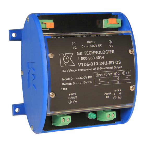
Model Number Key
VTD 1 - 010 - 24U - BD - OS
HOUSING:
OS - Oval DIN Mtg.
OUTPUT TYPE:
BD - Bidirectional
POWER SUPPLY:
24U - 24 VAC/DC
OUTPUT:
005 - +/-5VDC
010 - +/-10VDC
VOLTAGE INPUT RANGE:
0 - 15VDC
1 - 25VDC
2 - 50VDC
3 - 150VDC
4 - 300VDC
5 - 600 VDC
SENSOR TYPE:
VTD -
DC Voltage Transducers
Know Your Power
Other NK Technologies Products Include:
AC & DC Current Transducers
AC & DC Current Operated Switches
1φ & 3φ Power Transducers
Current & Potential Transformers (CTs & PTs)
3511 Charter Park Drive, San Jose, CA 95136
800-959-4014 or 408-871-7510 Phone
408-871-7515 FAX
sales@nktechnologies.com, www.nktechnologies.com
INSTRUCTIONS
VTD-BD SERIES
Bidirectional DC Voltage Transducers
+/-5 or +/-10VDC Output
Quick "How To" Guide
1. Ensure correct sensor model was chosen for Input Volt-
age of application.
2. Mount the sensor to a DIN rail using integrated mounting
clip on backside of transducer or secure using the tabs
in each corner.
3.
Connect monitored voltage to term. (2) & (1) and out-
put wiring using 22-16 AWG copper wires insulated to
75/90°. Lift the orange clip on the terminal, insert wire
and allow it to clamp on the stripped end of the wire.
Refer to "Output Wiring" section for voltage and imped-
ance recommendations.
IMPORTANT: Monitored voltage (V1/V2) polarity sensi-
tive for output polarity.
4. Connect 24VAC or DC power supply fused to 5 amp to
term. 3-4. Use twisted pair for CE compliance.
5. Connect output to the load using terminal 6 for the output
signal, and terminal 5 to common.
6. Energize primary circuit and sensor power.
VTD-BD Instruction Sheet Rev 1 01/17 P/N 292180021
Advertisement
Table of Contents

Summary of Contents for NK VTD-BD Series
- Page 1 CE compliance of the product: 2. Mount the sensor to a DIN rail using integrated mounting The VTD-BD series are designed to comply with EN 61010-1 clip on backside of transducer or secure using the tabs CAT III 600V max measurement category. Use 24 V input power in each corner.
- Page 2 Troubleshooting Tips Output Wiring . Transducer has no output VTD-BD Series Voltage Transducers are designed to moni- Connect control or monitoring wires to the sensor. Use up to A. Power supply is not properly sized. Check power supply tor DC voltage and detect conditions where supply voltage 14 AWG copper wire insulated to 75/90°C and tighten termi-...
Need help?
Do you have a question about the VTD-BD Series and is the answer not in the manual?
Questions and answers