Advertisement
Quick Links
Please read all instructional literature carefully and thoroughly before starting. Refer to the final page for the listing of Recommended
Practices, Liabilities and Warranties.
GENERAL
55 HT Series Thermostats are designed to control heat
tracing and freeze protection circuits. Temperature varia-
tions are sensed by a liquid filled sensing bulb which
hydraulically transmits to a diaphragm which either actu-
ates or deactuates a snap-acting switch at a predeter-
mined set point.
MAXIMUM TEMPERATURE IS THE HIGHEST
TEMPERATURE TO WHICH A SENSING ELE-
MENT MAY BE OCCASION- ALLY SUBJECTED
WITHOUT ADVERSELY AFFECTING SET POINT CALI-
BRATION AND REPEATABILITY. MAXIMUM TEMPERA -
TURE LIMITS STATED IN LITERATURE MUST NEVER
BE EXCEEDED, EVEN BY SURGES IN THE SYSTEM.
OCCASIONAL OPERATION OF UNIT UP TO MAX. TEM-
PERATURE IS ACCEPTABLE (E.G. START-UP, TEST-
ING).
CONTINUOUS OPERATION SHOULD BE
RESTRICTED TO THE DESIGNATED ADJUSTABLE
RANGE.
Part I - Installation
Part I - Installation
MOUNTING
INSTALL UNIT WHERE SHOCK, VIBRATION
AND TEMPERATURE FLUCTUATIONS ARE MIN-
IMAL. ORIENT UNIT SO THAT MOISTURE IS
PREVENTED FROM ENTERING THE ENCLOSURE.
Do not mount unit in ambient temperatures exceeding
product specifications. 55 Series Thermostats can be
mounted in any position.
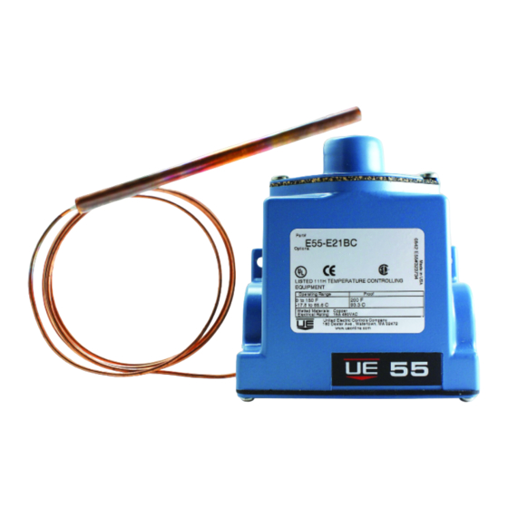
For remote sensing thermostats, mount the unit via the (2)
3/16" screw clearance holes on the enclosure (See
Dimensions on back page.) Locate the bulb and 6" of
55HT Series
Thermostats for Heat Tracing
and Freeze Protection Applications in
Ordinary
Locations
Type E55HT
Tools Needed
Flathead screwdriver
U N I T E D E L E C T R I C
C O N T R O L S
Installation and
Maintenance Instructions
capillary in the area that is exposed to the coldest tempera-
ture. Be sure to locate the bulb so that it will not be
exposed to temperatures beyond sensor exposure limits.
Avoid bending or coiling the capillary tube smaller than
1/2" radius. Exercise caution when making bends near the
capillary ends.
For ambient sensing thermostats, locate the unit in area
that is exposed to coldest temperature.
WIRING
DISCONNECT ALL SUPPLY CIRCUITS BEFORE
WIRING UNIT. ELECTRICAL RATINGS STATED
IN LITERATURE AND NAMEPLATES MUST NOT
BE EXCEEDED. OVERLOAD ON A SWITCH CAN
CAUSE FAILURE ON THE FIRST CYCLE. WIRE UNITS
ACCORDING TO NATIONAL AND LOCAL ELECTRICAL
CODES. RECOMMENDED WIRE SIZE IS 14 AWG.
Remove the four screws retaining the cover and cover gasket.
Connect conduit to the 1/2" NPT connection located on the
side of the enclosure. Wire directly to the switch terminals
according to local and national electrical codes. The three
switch terminals are clearly labeled "common", "norm
open", and "norm closed".
Start-Up Process
Turn dial and knob to the desired temperature setting.
Thermostat is ready for operation.
IM55HT
Advertisement

Summary of Contents for United Electric Controls 55HT Series
- Page 1 IM55HT 55HT Series Thermostats for Heat Tracing U N I T E D E L E C T R I C and Freeze Protection Applications in C O N T R O L S Ordinary Locations Installation and Maintenance Instructions Type E55HT Please read all instructional literature carefully and thoroughly before starting.
- Page 2 RECOMMENDED PRACTICES AND WARNINGS Dimensions United Electric Controls Company recommends careful consideration of the following factors when specifying and installing UE pressure and temperature units. Before installing a unit, the Installation and Maintenance instructions provided with unit must be read and understood.