Advertisement
Quick Links
ZCM-11, ZCM-11/U TIME PROGRAMMER
WEEK'S - SINGLE-CHANEL
Zakład Mechaniki i Elektroniki
ZAMEL sp.j.
J.W. Dzida, K. Łodzińska
ul. Zielona 27, 43-200 Pszczyna, Poland
Tel. +48 (32) 210 46 65, Fax +48 (32) 210 80 04
www.zamelcet.com, e-mail: marketing@zamel.pl
DESCRIPTION
TECHNICAL DATA
Programmable control timers are de-
ZCM-11
signed for time functions execution in
Power supply terminals: A1, A2
automatics and control systems. Week's
programmer controls the output relay in de-
ZCM-12: 230 V AC~(-15 ÷ +10 %)
Input rated voltage:
ZCM-12/U: 24 ÷ 250 V AC, 30 ÷ 300 V DC
pendence of program settings (day, hour).
The device is fi tted with some additional
Nominal frequency: 50 / 60 Hz
functions, among other things the random
Rated power consumption: 2 W / 14 VA
function that is used for the operating mode
Number of channels: 1
changing by means of an external push
Program quantity: 400 (200 On/Off pairs)
button. It is possible to mount the device
Program: daily, week's
on TH 35 rail and seal it if needed. A simple
menu layout and an ergonomic keyboard
Operating modes: manual, automatic, random, impulse
enable easy and intuitive unit operating.
Change of season summer/ winter: automatic, manual
The construction of the system guar-
Colour of LCD panel lighting: amber
antees supporting of all the settings
Input: yes
with battery energy when the electric
Accuracy of time measurement: max ±1 s / 24 h at temp. 25 °C
power supply is off.
Time of clock maintenance: 3 years
CAUTION:
Time of programme maintenance: 10 years
Before installing
Clamps of release system: IN, IN, IN, IN
the device in the
Receiver input (supply) terminals: 11, 12, 14
switchboard
Output relay parameters: 1 NO/NC-16 A/250 V AC1 4000 VA
or starting the
Number of terminal clamps: 12
system operation
in order to pro-
Section of connecting cables: 0,2 ÷ 2,50 mm
gramme it, the
Ambient temperature range: -20 ÷ +60
battery security
Operating position: freely
separator should
Mounting: rail TH 35 (PN-EN 60715)
be removed against
Protection degree: IP20 (PN-EN 60529)
discharging.
Protection level: II
Overvoltage category: II
FEATURES
Pollution degree: 2
Dimensions: double-modular (35 mm) 90x35x66 mm
● Week's cycle control in dependence of
Weight: 0,140 kg
the current hour,
● Double-module casing with a protection
Reference standards: PN-EN 60730-1; PN-EN 60730-2-7
flap,
PN-EN 61000-4-2,3,4,5,6,11
● Random op mode, additional control
input IN,
● Many programmes enabling various
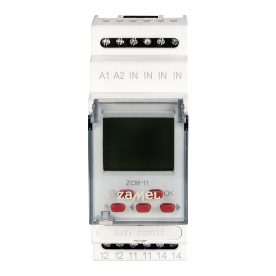
APPEARANCE
applications,
● LCD display illumination,
● Mounted on TH 35 rail.
Power terminals
(A1, A2)
The device should be connected
to a singlephase system accor-
ding to current standards. The
device connections will be descri-
bed in this manual. Only qualifi ed
CAUTION
electricians are allowed to mount,
LCD display
connect and adjust the device. It is necessary
to read this manual and know the unit functions
before the device mounting. Do not disassembly
the device casing or you will lose any warranty
rights and expose yourself to the electric shock
hazard. Before mounting operation make sure
Control buttons
of disconnecting the connection wires from the
electric network. Use a cross-head screwdriver
of 3.5 mm diameter to mount the device. The
relay should be carried, stored and used in an
appropriate way. Do not mount the device in
case of any device parts lack, damage or defor-
mation. In case of malfunction please notify the
Relay output terminals
manufacturer.
(12, 12, 11, 11, 14, 14)
DESCRIPTION
INSTRUCTION MANUAL
MAIN MENU
2
C
o
DATE SETTING
Trigger terminals
(IN, IN, IN, IN)
Automatic mode
Manual mode
Random mode
Winter/summer time
Week's day
Relay state
Info fi eld
Current time (hh:mm:ss)
The symbol means selective collecting
of electrical and electronical equipment.
It is forbidden to put the used equipment
together with other waste.
VER. 002_21.09.2009
Description of elements and messages displayed
- days of week
- day,
- year
- transmitter's status
- program setting
- automatic mode
- current time setting and summer/winter time shift
- manual mode
- current date setting
- random mode
- random mode setting
- impulse mode
- extenal input setting
- external input
- impulse mode setting
- winter time
- automatic,
- user
- summer time
- on/off
Button description
• in the main window - the automatic mode enter or relay state changeover, if the timer already in the automatic
mode;
• in the main window (3 seconds) - the random mode enter / exit;
• in the random mode - randomizing active/inactive manual toggle;
• the other windows - exit to a higher level without changes saving;
• in the main window - the manual mode enter or the relay state changeover, if the timer already in the manual mode;
• in the random mode - the relay state changeover and randomizing switch-OFF;
• the other windows - exit to a higher level without changes saving;
• in the main window - the main menu enter;
• the other windows - a submenu enter or setting acknowledgement;
• window/option toggle or set value increase/decrease;
Menu enter by pressing OK;
menu items scrolling by means of cursors
.
Function
Description
PROGRAM SETTING
CURRENT TIME SETTING
CURRENT DATE SETTING
WINTER/SUMMER TIME SETTING
RANDOM MODE SETTING
EXTERNAL INPUT SETTING
IMPULSE MODE SETTING
- Current date setting; entry after pressing OK;
YEAR - choose adequate year with cursors
confi rm with OK, range of
years: 2000÷2099;
MONTH - choose month with cursors
confi rm with OK;
DAY - choose day with cursors
confi rm with OK; the system has a protec-
tion against introducing incorrect parameter of a day for a given month (it
takes into account leap years and it automatically calculates the day of the
week on the basis of an arranged date);
Confi rmation causes movement to a date setting window and set-up of cur-
rent summer/ winter time - if the option
is arranged.
It is possible to exit every submenu window in any moment without sav-
ing settings by pressing the button
or .
TIME SETTING
- setting the current clock time; entry after pressing
OK;
HOUR- choose adequate hour with cursor
set in 1-24
with OK;
MINUTES - choose adequate parameter of minutes with cur-
sors
confi rm with OK;
Confi rmation of the parameter of minutes causes simultane-
ous nullifi cation of the parameter of seconds and movement to
the window of time setting.
It is possible to exit every submenu window in any moment
without saving settings by pressing the button
WINTER / SUMMER TIME SETTING
- winter/summer time toggle mode selection:
automatic time changing on the last March Sunday, at 2:00
into summer time and on the last October Sunday, at 3:00 into
winter time,
user; option entering after pressing OK;
MODE SETTING - with
edge with OK; after selecting
be toggled automatically; after selecting
enter the next window;
With
select winter/summer, where
summer time; if the time icon is changed, the timer will correct
the current time appropriately; acknowledge by pressing OK;
After time mode selecting winter/summer time change window
will be open.
OPERATING MODE CHANGE (AUTOMATIC, MANUAL, RANDOM)
MANUAL OP MODE TOGGLE - if the main window is open
and the timer is in the automatic mode
force the unit to toggle into the manual mode and the relay
state changeover;
Successive key pressing will force the relay state changeo-
ver without the op mode;
AUTOMATIC MODE TOGGLE - if the main window is open
and the timer is in the manual mode pressing key
the unit to toggle into the automatic mode and the relay state
changeover;
Successive
over without the op mode;
RANDOM MODE TOGGLE - in order to enter the random
mode it is necessary to press and hold
Continuous light
range where ON/OFF states randomizing is to be active, and
the pulsing light indicates that the unit is randomizing ON/
OFF states according to RANDOM MODE SETTING menu
settings; pressing key
and the relay state changeover ( pulsing
MODE SETTING menu settings are still binding; successive
pressing
Pressing
ing switch-OFF, if it was active (
mode exit is possible by pressing and holding
Randomizing activity/inactivity update is being operated either
in automatic or manual mode.
which you can
or 1-12
(AM) and 1-12
(PM)format; confi rm
or .
-
- winter/summer timer toggle manual, by
select
or
acknowl-
, winter/summer time will
mode you will
is winter time,
-
pressing key
will
will force
key pressing will force the relay state change-
key for 3 secs;
iindicates that the timer is not in the time
orces randomizing ON/OFF states
), and RANDOM
key forces randomizing to be OFF;
key forces the relay changeover and randomiz-
is lighting). The random
for 3 secs. .
Advertisement

Related Manuals for Zamel EXTA ZCM-11


Summary of Contents for Zamel EXTA ZCM-11
- Page 1 Tel. +48 (32) 210 46 65, Fax +48 (32) 210 80 04 the window of time setting. - winter time www.zamelcet.com, e-mail: marketing@zamel.pl - automatic, - user - summer time...
- Page 2 4. ZMIE ZAMEL SP. J. is liable for processing any claim according to current Polish legislation. After a while, the clock will automatically set date and time. 5. ZMIE ZAMEL SP. J. shall process the claim at its own discretion: product repair, replacement or money return. If selected set with cursors impulse duration time in seconds;...