Advertisement
Quick Links
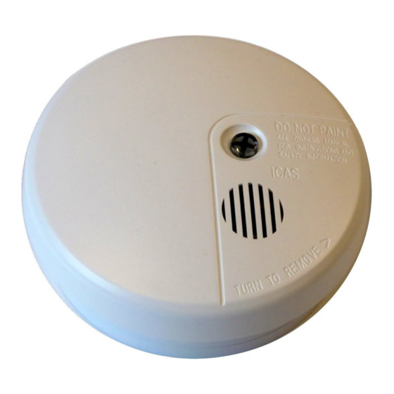
Fig. 1: Detector 500-IDx, x: O=Optical, I=Ionic, T=Temp.
Description
ICAS Model 500-IDx is a system detector series to be connected with a
standard EN54 classified fire central. The detectors are equipped with
digital signal handling and advanced filter and automatic adjustment of
sensitivity. The detector series is developed for dwellings, accommodation,
bed and breakfast places, offices etc. as a system detector connected to an
EN54 fire central.
When the detector moves from normal to fire alarm, then the current will
increase. OPTO-output will be activated and the RED led have fixed light
until the detector is reset.
The detector has an integrated siren (85db/3m), which is controlled from
the fire central or locally from the detector via terminal OPTO. This will be
switched to 0V when the detector goes into alarm.
Automatic Testing & Sensitivity control (ATS)
Improved reliability by introducing Automatic Test and Sensitivity control
to keep the sensitivity at the correct level during the lifetime of the detector.
The built in micro-controller is also used to communicate with an integrated
diagnostic system DS500, as well as handling all internal test and
diagnostics. The detector sends signal fault via LED's (ref. table page 2).
Advanced Digital Signal-filtration (ADS)
This solution guarantees a correct signal handling and reduce nuisance,
false alarms and give improved immunity against EMC. All the important
events, i.e. alarms and fault, will be saved to a memory, which can save the
last 32 events in order of appearance. It has no clock function.
Read the events in each detector from your PC!
Optional equipment Diagnostic System DS500 for checking the detectors
via usb-input on your PC. DS-500 is used to read the data from the detector
memory (eeprom) in a service situation. The system will identify the
detector and all the data will be sent to the PC for investigation by service
people, be printed, sent to service-centre or saved.
500-IDX series type of detectors:
500-IDI: Ionical chamber, environmental friendly! (3kBq only)
500-IDO: Optical chamber
500-IDT: Heat detector with fixed temp. + Rate of Rise function
Terminal-description:
1:
+U
(Connection + terminal 9V-24V DC)
2:
0V
(0V connection to next detector in loop)
3:
0V
(0V from fire central)
4:
OPTO (Open collector (in alarm drop to 0V)
5:
-SIR (Sirene -)
6:
+SIR (Sirene +)
Note: 0V-connectors (connector 2 & 3) make it possible to supervise that
the detector is connected in the loop
www.icas.no
Conventional Fire Detectors with Siren!
Manual_500-IDx_Eng.doc
500-IDx
Fig 2: Standard Base and release mechanism
Installation
1. Choose the best place to fix the detector. It shall be mounted in the
ceiling. Min. 0,5m from walls, max. 1,5m from bedroom door and
min. 1m from light point or other electrical equipment or ventilation
outlet/fans.
2. Use 2 screws to fix the base and terminate the cable to terminals.
Use terminal 3 (0V) from fire central and terminal 2 (0V) for next
detector. This to obtain loop fault if a detector is not in its base.
Note! Valid only for supply from fire central where it's used
common wires for power and alarm.
3. Place the detector head in the Base by aligning the two marks, see
fig 2. Then turn the head clockwise approx. until locked.
4. Repeat 1–4 for all the detectors in the system.
5. Do not start up the detectors in an environment with smoke. (The
sensitivity can be wrongly set).
6. Turn on the power at fire central.
7. During the start up time, the detector will give 2 short yellow blink
every 4. sec. in 40 sec. dependent of the detector in the 500-IDX
series.
8. To remove the detector, use a small screwdriver into the locking
opening in the base. (See fig 2), and turn anti-clockwise.
Fig 3: Relay Base. (7=Nc, 8=Com, 9=No)
Relay Base:
If a relay is needed i.e. for use with a burglar alarm system or to control
external signals, a relay base is used.
rev. 24.03.11
Side 1/5
Advertisement

Summary of Contents for ICAS 500-ID Series
- Page 1 Description Installation ICAS Model 500-IDx is a system detector series to be connected with a 1. Choose the best place to fix the detector. It shall be mounted in the standard EN54 classified fire central. The detectors are equipped with ceiling.
- Page 2 0,5A v/125Vac, 1A v/30VDC Max breaking current: Max Power: 125VAC, 48VDC Max Breaking Power: 62,5VA, 33W Temp: C to +55 Dimensions: D=104mm, H=12mm, (build 6mm only when mounted to detector) Humidity: 95%RH (No condensation) www.icas.no Manual_500-IDx_Eng.doc Side 2/5 rev. 24.03.11...
-
Page 3: Control Unit
Control unit IMC-ME IMC-ME Z1 - 12V (22k) Z2 - 12V (0V) (0V) (0V) (+U) (0V) (+U) (0V) (+U) (0V) +SIR OPTO OPTO OPTO +SIR +SIR -SIR -SIR -SIR +12V Detector Detector Detector 500-ID(x) 500-ID(x) 500-ID(x) www.icas.no Manual_500-IDx_Eng.doc Side 3/5 rev. 24.03.11... - Page 4 (+U) (0V) (+U) (0V) Sounders +SIR OPTO +SIR OPTO +SIR OPTO Alarm 4 -SIR -SIR -SIR Alarm 3 Alarm 2 Alarm 1 Detector Detector Detector 500-ID(x) 500-ID(x) 500-ID(x) Error- output Alarm- output Input Output www.icas.no Manual_500-IDx_Eng.doc Side 4/5 rev. 24.03.11...
- Page 5 9: NO Loop 9: NO 8: COM 8: COM 8: COM 7: NC 7: NC 7: NC +SIR OPTO +SIR OPTO +SIR OPTO -SIR -SIR -SIR Siren output Detector Detector Detector 500-ID(x) 500-ID(x) 500-ID(x) www.icas.no Manual_500-IDx_Eng.doc Side 5/5 rev. 24.03.11...