Advertisement
Quick Links
Z
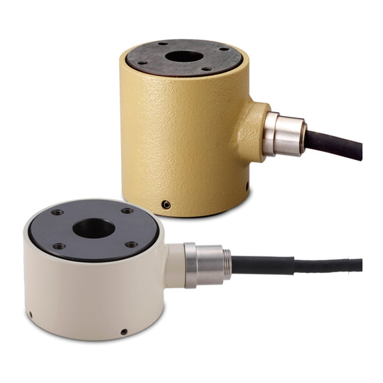
Strain gauge load cell Instructions for Use
TC-XR(T)-G6
TC-KR(T)-G6
Compression Load Cell
Introduction
Thank you for purchasing the TC-XR(T)-G6/TC-KR(T)-G6
load cell.
Please read this document completely before using this
load cell to achieve its best performance and ensure safe
and proper operation.
Included accessories
If anything is missing or damaged, contact the retailer
where you purchased the product.
Test report × 1
Instructions for Use (this document) × 1
o Company names and product names in this document are the
trademarks or registered trademarks of their respective owners.
IMPORTANT SAFETY INSTRUCTIONS
V
WARNING
If something abnormal occurs
In the unlikely event that the product produces smoke, a
strange smell or noise, for example, continuing to use it in
this abnormal state could cause fire or electric shock. After
Precautions when placing loads on the
unit
o If the load receiving area is contacted by something that
is at a different temperature and the load is increased,
the values output by this device could become unstable,
making accurate measurement impossible. In such a
case, wait until the temperature difference ceases to
exist before measuring.
o Make sure the load is perpendicular to the surface to
which this unit is attached.
o Place the load so that it is centered on the center of the
unit. If the load is not centered (eccentric load), twisting,
for example, and measurement errors could occur. This
could even result in damage.
F1
F F2
F is the correct load orientation
F1 is an eccentric inclined load
F2 is an eccentric load
o Be careful to avoid turning and twisting from lateral
loads. This could cause troubles like those described
in the previous item.
o Be careful to avoid applying loads that exceed the
rated capacity. In particular, use caution when there are
vibrations because loads that exceed the rated capacity
could occur due to sympathetic vibrations, for example.
o These products are made with coaxiality and perpen-
dicularity tolerances of 0.02 mm for the center hole and
the top and bottom surfaces. When using them, please
consider attachment methods as well as jigs and other
D01197201A
cutting off the power, confirm that smoke is no longer being
produced. Then, request repair from the retailer where you
purchased the product.
Do not open the cover.
Never remove the cover from this unit. Doing so could
cause electric shock. Request inspection and repair from
the retailer where you purchased the product. Do not
alter this unit. Doing so could cause fire or electric shock.
Do not put foreign objects or water, for example,
into the unit.
Do not place a container that holds water, for example,
on top of this unit. Liquid overflowing or entering the unit
could cause fire or electric shock.
Do not use the unit with any power supply voltage
other than that specified.
Do not use the unit with any power sup ply voltage other than
that specified. Doing so could cause fi re or electric shock.
V
CAUTION
Unsuitable installation locations
Do not place the unit in the following types of locations.
Doing so could cause fire or electric shock.
o Locations where it might be exposed to smoke or steam,
such as near a kitchen table or humidifier
o Unstable locations, including unsteady stands and
tilted places
o Location that are very humid or dusty
o Locations that are exposed to direct sunlight
When not using the unit for a long time
For safety, cut the power supply when not using this unit
for a long time.
Do not operate a damaged unit.
Precautions for use
o This unit is not built to be water or splash resistant,
and it cannot be used in conditions when the relative
humidity is high. Moreover, use in atmospheres with
corrosive gases should be avoided.
o Avoid use in conditions where condensation could occur.
parts being used so that coaxiality and perpendicularity
tolerances of 0.02 mm are maintained.
o Use load cells so that loads are distributed evenly across
the entire surfaces of both the top and bottom.
Electrical connection of load cell with
built-in TEDS
o Connect as shown in the illustration below. Incorrect con-
nections could result in inability to balance and in errors
occurring in the output voltage when loads are applied.
Using a cable with bare lead wires
TEDS
o This unit has a built-in TEDS function.
o The orange and green cores in the cable and the F and
G pins in the connector are wired for TEDS.
o This unit does not support remote sensing.
o Since products that support remote sensing use the
same cables and connector pins as TEDS, be careful not
to try mistakenly to use these pins for remote sensing.
o See the operation manuals of indicators and strain amps
that support remote sensing for how to connect sensors
with those units.
o The shield is not connected to the main body of this
product. For this reason, if grounding is necessary because
o Connect cores to the load cell after discharging (elim-
inating) static electricity from your body.
o Be careful to prevent water, oil and other substances
from getting on the unit.
o If the surrounding temperature changes suddenly, the
values output by this device could become unstable,
making accurate measurement impossible. (This could
occur, for example, in a location blown by warm or cold air.)
Installation procedures
o Install this unit in a place where the structure is level
and can sufficiently bear the load being used.
o Screw holes for installation are located in four places
each on the top and bottom surfaces.
o The top and bottom screw hole dimensions are different
according to the load cell rated capacity. The screw hole
dimensions are shown in the tables below.
TC-KR(T)-G6
Rated
capacity
5 kN
10 kN
20 kN
30 kN
50 kN
100 kN
200 kN
300 kN
TC-XR(T)-G6
Rated
capacity
20 kN
50 kN
100 kN
200 kN
300 kN
of external noise, for example, arrange to ground the
shield to a part other than the body of this unit.
o Since the cable is directly connected to this unit, use a
specialized cable to increase the length. (Please consult
with us.)
o When conducting insulation resistance tests, limit them
to the red, black, blue and white cores. Do not apply to
the TEDS cores (orange and green).
Using a connector (optional)
Red
Input (+)
Black
Output (−)
Blue
Input (−)
White
Output (+)
TEDS
Orange TEDS signal (+)
Green
TEDS signal (COM)
Yellow
Shield
Precautions when using during calibra-
tion or as a master load cell
Please take the following precautions when calibrating one of
these products yourself or when using one as a master load cell.
o We recommend attaching plates to the top and bottom
sides and using them when applying loads.
o Consider rigid materials and their hardness for the
plates used for top and bottom so that they are able
to maintain the flatness and parallelism of the load cell
in relation to the load.
Screw hole
Screw hole
Tightening
dimensions
depth
torque
M4X0.7
8 mm
3.6 N·m
M5X0.8
8 mm
7 N·m
M5X0.8
8 mm
7 N·m
M5X0.8
8 mm
7 N·m
M5X0.8
8 mm
7 N·m
M5X0.8
8 mm
7 N·m
M8X1.25
12 mm
29.5 N·m
M8X1.25
15 mm
29.5 N·m
Screw hole
Screw hole
Tightening
dimensions
depth
torque
M5X0.8
8 mm
7 N·m
M5X0.8
8 mm
7 N·m
M5X0.8
8 mm
7 N·m
M8X1.25
12 mm
29.5 N·m
M8X1.25
15 mm
29.5 N·m
A Input (+)
B Output (−)
C Input (−)
D Output (+)
F TEDS signal (+)
G TEDS signal (COM)
E Shield
NDIS-compatible connector
Advertisement

Related Manuals for Teac TC-XR(T)-G6

Summary of Contents for Teac TC-XR(T)-G6
- Page 1 The screw hole Introduction that specified. Doing so could cause fi re or electric shock. dimensions are shown in the tables below. Thank you for purchasing the TC-XR(T)-G6/TC-KR(T)-G6 CAUTION TC-KR(T)-G6 load cell. Unsuitable installation locations...
- Page 2 Example of jig for TC-XR(T)20KN-G6 and TC-XR(T)50KN-G6 TEAC indicators that support TEDS include the TD-01 Portable, TD-700T, TD-260T, TD-275T and TD-280T. For details, inquire 4 × Ø5.5 through, Perforations at a shop that handles these products.