Advertisement
Quick Links
IO&M Guide
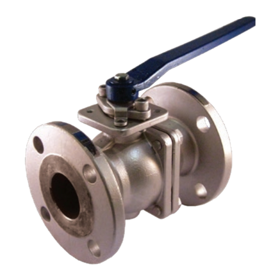
FL-CS-100-150 & FL-SS-100-150, FL-CS-100-300 & FL-SS-100-300
1. Before Installation
1.1 Fluid thermal expansion:
Pressure, built-up in the body cavity by
heating volatile fluid, can damage the
seats or the ball. The hole in the ball beneath
the stem slot will equalize pressure between
body cavity and the pipeline when valve is in
the open position.
1.2 Anti-Static device:
Jomar's Flange Series ball valves are provided
with anti-static devices for ball-stem-body.
When service conditions require electrical
continuity to prevent static discharge, the user
is responsible for specifying static grounding.
1.3 Throttling service:
Ball valves are generally not recommended for
throttling service, where both the fluid flow
and the leading edge of the ball can damage
or deform the resilient ball seats causing
leakage. High fluid velocity or the presence
of solid particles in suspension will further
reduce seat life. These valves are not intended
to be operated in a partially open position.
1.4 Do not open the bonnet or cap when
valve is under pressure. Valve is not equipped
with pressure access device.
1.5 Do not touch the surface of the valve
on high temperature applications.
1.6 Not suitable for unstable fluid.
1.7 Locking device on the handle to avoid
unauthorized operation is optional.
Note: Information subject to change without notice.
1
© 2020 Jomar Valve • www.jomarvalve.com • P: (586) 268-1220 • F: (586) 979-8315
061920
2. Installation and Operation
2.1
Handling
During installation, larger valves require a
hoist to lift both sides of the body.
2.2
Cleaning
Even if valves were transported in a clean
environment, installers must check for any
foreign body or dust inside the bore. If any,
clean thoroughly before installation. Installers
to clean valves with water, compressed air, or
steam (automated valves should be cleaned
only with water or steam, compressed air is not
allowed.) For cleaning, first step is to stand the
valve with bore perpendicular to the ground and
clean, ensuring all foreign matter is removed
from the bore. Then check and clean the
connecting pipe bores and flange faces.
2.3 Valve Installation
a. Direction
Ball valves are normally bi-directional, i.e. no
preferred flow direction.
b. Position
The valves weight bearing ability and
gradient are very important to the pipe
installation. Do not allow the pipeline stress
to be transmitted to valve flanges and cap. It
could cause body deformation and seat leakage.
c. Bolt tightening of flanged ends. The force
must be evenly spread. Tightening order for
flanged ends is given below.
2.4
Operation
a. For manual operation, turn the lever in
counter clockwise to close and clockwise to
open. If the handle is parallel to the pipeline, the
Advertisement

Summary of Contents for JOMAR FL-CS-100-150
- Page 1 If the handle is parallel to the pipeline, the © 2020 Jomar Valve • www.jomarvalve.com • P: (586) 268-1220 • F: (586) 979-8315 Note: Information subject to change without notice. 061920...
- Page 2 3) Remove No. 11-1 gland bolts., remove e. Repair kits are available by contacting No. 10 gland flange. Jomar. © 2020 Jomar Valve • www.jomarvalve.com • P: (586) 268-1220 • F: (586) 979-8315 Note: Information subject to change without notice. 061920...
- Page 3 5” 5/8”-11UNC 14UNC 6” 5/8”-11UNC 3” 1/2”-13UNC 8” 5/8”-11UNC 4” 5/8”-11UNC 1850 3/4”-10UNC 3500 5” 1”-8UNC 5800 6” © 2020 Jomar Valve • www.jomarvalve.com • P: (586) 268-1220 • F: (586) 979-8315 Note: Information subject to change without notice. 061920...