Advertisement
Quick Links
I N STRU CT I ONS
Type ETV-P with dry contact
57937A - 05/11 (MBC)
English
APPLICATION
Control of electrical heating, floor, ceiling and
radiant.
PRODUCT PROGRAMME
ETV with scale range 0/+40°C, 230V AC
ETV-1991-P
Incl. floor sensor 2.5 m
FUNCTION
The temperature is set to the required
temperature and the heating output is
energised/de-energised with a difference of only
0.4°C. LED indication when the relay is
energised.
CE MARKING
OJ declare under their own responsibility that
this product meets the requirements of the
European Council's Directive 89/336 and
successive modifications as to electro-magnetic
compatibility and the Council Directive 73/23 as
to electrical equipment to be applied within
certain voltage ranges.
Standards applied
EN 50 081-1, EN 50 082-2, EN 60 730-1 and EN
60730-2-9.
The product may only be energised when the
entire installation meets the current directive
requirements.
When the product is installed according to this
instructions guide and the current installation
guidelines, it is covered by factory guarantee.
If the product has been exposed to damage e.g.
in transport, it must be checked and overhauled
by qualified staff before the product is
connected to the power.
TECHNICAL DATA
Supply voltage
ETV-1991-P . . . .230V AC, ±10%, 50-60 Hz
Max. fuse . . . . . . . . . . . . . . . . . . . . . . . . . . .16A
Output relay . . . . . . . . . . . .S.P.S.T., dry contact
16A, max. 3.6 kW
On/Off difference . . . . . . . . . . . . . . . . . . . .0.4°C
Operation temperature . . . . . . . . . . . . .0/+50°C
Power consumption . . . . . . . . . . . . . . . . . . .3 VA
Weight
. . . . . . . . . . . . . . . . . . . . . . . . . . . .90 g
Dimensions (HxBxW) . . . . . . . . . .86x36x58mm
Housing . . . . . . . . . . . . . . . . . . . . . . . . . . .IP 20
Temperature sensor . . . . . . . . . .NTC-thermistor
CLASSIFICATION
The product is a Class II product (reinforced
insulation) and the product must be connected
to the following conductors:
1)
Phase
(F/L1)
2)
Neutral
(N/L2)
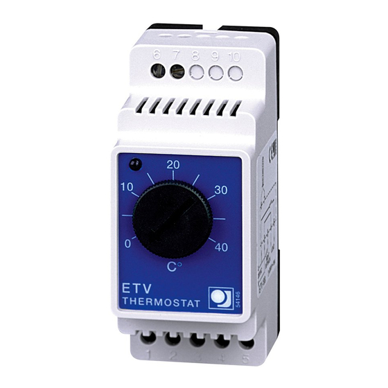
TEMPERATURE SETTING
ETV has a scale range of 0/+40°C. Red LED
indication when heat is on. The thermostat is
set on max. temperature, until the required room
temperature has been reached. Then the
thermostat is turned down until the LED turns
off. After 1-2 days a fine adjustment may be
required.
INSTALLATION
ETV is mounted on a DIN-rail, cover box for wall
mounting is obtainable as extra equipment.
Connection according to figure 1.
Floor sensor: Is mounted in standard conduit
embedded into the floor, and positioned
between the heating cables - and preferably as
close to the floor surface as possible. If
required, the sensor cable can be extended up
to 100 m with standard installation cable.
Room sensor: The sensor is positioned on the
wall in such a way that there is free air
circulation above it. Furthermore it should be
placed in such a way that its position is not
influenced by any form of heating outlet (e.g.
the sun) draughts from doors or windows or by
the outside temperature (outside wall).
Sensor cable: The sensor cable must not run in
trunking or in bundles together with other
circuits. The sensor cable should not be laid
parallel to cables which may induce
signals/noise to the sensor signal and thus
disturb the functioning of the thermostat.
CONNECTION (fig. 1)
OJ Electronics A/S
Stenager 13B · DK-6400 Sønderborg
Tel +45 73 12 13 14 · Fax +45 73 12 13 13
www.ojelectronics.com · oj@ojelectronics.com
© 2011 OJ Electronics A/S
Deutsch
ANWENDUNG
Regelung von elektrischen Heizelementen in
Boden und Deckenheizungen, sowie für
Heizkörper.
PRODUKTPROGRAMM
ETV mit Skalenbereich 0/+40°C, 230V AC
ETV-1991-P
Einschl. Bodenfühler 2.5 m
FUNKTION
Der Thermostat wird auf die gewünschte
Temperatur eingestellt und die Heizleistung wird
mit einer Differenz von nur 0,4°C ein-
/ausgeschaltet. Eine Leuchtdiode leuchtet auf,
wenn das Relais aktiviert ist.
CE PRÜFZEICHEN
OJ erklärt in eigener Verantwortung, dass
dieses Produkt der Direktive des Europäischen
Rats 89/336 und den nachfolgenden
Änderungen betreffs elektromagnetischer
Kompatibilität sowie auch der Direktive des
Rats 73/23 betreffs Elektroausrüstung zur
Anwendung innerhalb gewissen
Spannungsgrenzen entspricht.
Berücksichtigte Standards
EN 50 081-1, EN 50 082-2, EN 60 730-1 und EN
60730-2-9.
Das Produkt darf erst in Betrieb genommen
werden, nachdem sichergestellt ist, dass die
Gesamtinstallation die geltenden Forderungen
der Direktive erfüllt.
Nachdem das Produkt nach den Anweisungen
dieser Bedienungsanleitung und den
Installationsvorschriften montiert ist, ist es von
der Werkgarantie umfasst.
Ist das Produkt z.B. im Transport beschädigt
worden, ist es vom qualifizierten Personal zu
besichtigen und zu prüfen, bevor das Produkt
ans Netz angeschlossen wird.
TECHNISCHE DATEN
Betriebsspannung
ETV-1991-P . . . .230V AC, ±10%, 50-60 Hz
Max. Sicherung . . . . . . . . . . . . . . . . . . . . . . .16A
Ausgangsrelais .S.P.S.T., potentialfreier Kontakt
16A, max. 3.6 kW
Ein/Aus Differenz . . . . . . . . . . . . . . . . . . . .0.4°C
Betriebstemperatur . . . . . . . . . . . . . . . .0/+50°C
Leistungsaufnahme . . . . . . . . . . . . . . . . . . .3 VA
Gewicht . . . . . . . . . . . . . . . . . . . . . . . . . . . .90 g
Abmessungen (HxBxD) . . . . . . . .86x36x58 mm
Gehäuseschutzart . . . . . . . . . . . . . . . . . . . .IP 20
Temperaturfühler . . . . . . . . . . . .NTC-Thermistor
CLASSIFICATION
Das Produkt ist ein Klasse II Gerät (verstärkte
Isolation) und das Produkt ist an die folgenden
Leiter anzuschliessen:
1)
Phase
(F/L1)
2)
Nulleiter
(N/L 2)
TEMPERATUREINSTELLUNG
ETV hat einen Skalenbereich von 0/+40°C. Als
Hilfe bei der Einstellung ist der Thermostat mit
einer Leuchtdiode versehen, die rot aufleuchtet,
sobald die Heizung eingeschaltet ist. Den
1
Advertisement

Related Manuals for OJ ETV-P Series


Summary of Contents for OJ ETV-P Series
- Page 1 Relais aktiviert ist. CE MARKING the outside temperature (outside wall). OJ declare under their own responsibility that CE PRÜFZEICHEN this product meets the requirements of the Sensor cable: The sensor cable must not run in OJ erklärt in eigener Verantwortung, dass...
- Page 2 Stenager 13B · DK-6400 Sønderborg Tel +45 73 12 13 14 · Fax +45 73 12 13 13 www.ojelectronics.com · oj@ojelectronics.com Fig. 2 HEAT The trademark is registered and belongs to OJ Electronics A/S · © 2011 OJ Electronics A/S...