Advertisement
Quick Links
ENGLISH
PRECAUTION NOTICE
1. DO NOT intend to remove the power supply cover and service it, high voltage inside the power supply, which
gives risk of electrical shock. The warranty will be void if the warranty sticker is removed, tampered or any
modification ofthe power supply.
2. The warranty is not covered with damage caused by improper operation or by uncontrollable natural forces, such
as lightning, earthquake, flood.
3. This power supply is designed for indoor use at 0~50℃ ambient, non-condensing environment.
Please keep your system in well ventilated area.
INSTALLATION STEPS
1. Please read your system component manual to know what kinds of DC connectors are needed to be applied and
other relative installation tips.
2. Place the power supply into the chassis corresponding location. To ensure ideal system ventilation, and do not
block power supply air intake and exhaust area.
3. Connect the DC connector to system component, if required. Do not need to plug the AC cord to power supply at
this stage yet.
4. Following table describes purpose of DC connectors. Connector types might differ by models.
8P or 4P CPU connector
(Some models offer 4-pin module detachable design):
For CPU power.
8P or 6P PCI-E connector
(Some models offer 2-pin module detachable design):
For graphic cards power.
Some advance motherboard requires not only 24-pin main power and 8-pin CPU connector, but also other
peripheral power connectors to share the current and increase the stability. We recommend applying the other
peripheral power connectors to it if your system consists of multiple graphic cards.
5. Plug the AC cord to the power supply, and turn the "I/O" switch to "I" location. Then your system is ready to
work.
SIMPLE TROUBLE SHOOTING
If the system cannot turn on, or always turn off right after you turn on the system, please process following
debug steps.
1. Please remove all DC connectors from the systems.
2. Use a metal clip to bridge 24-pin main power connector's green and any black terminal to perform "no load
operation".
2-1 If power supply fails to turn on, please contact us or agent for RMA process.
2-2 If power supply can turn on, this means it is normal. Please check again if your system components
are well installed, no short circuit to the motherboard terminal causing by any foreign object. Re-install
add-on cards or module if necessary. And plug all power supply connectors back to system and try
again to boot the system again.
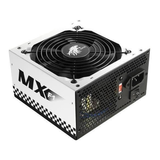
Thank you for choosing LEPA power supply. Please read this
manual before installing the power supply into the system.
24P main power connector
(Some models offer 4-pin module detachable design):
For motherboard main power input and "I/O" control.
4P peripheral connector.
For peripheral device power.
SATA connector.
For most SATA interface
peripheral power.
4P Floppy connector
For Floppy drive power.
Advertisement

Related Manuals for Lepa MX 550W


Summary of Contents for Lepa MX 550W
- Page 1 ENGLISH Thank you for choosing LEPA power supply. Please read this manual before installing the power supply into the system. PRECAUTION NOTICE 1. DO NOT intend to remove the power supply cover and service it, high voltage inside the power supply, which gives risk of electrical shock.
- Page 2 感谢您购买利豹电源供应器,将电源供应器安装于系统前请详读说 中 文 明书。 注 意 事 项 1. 用户不得擅自打开电源供应器上盖并自行维修,内有高压电,可能会遭受电击。若保修贴纸移除、破损或自行修改 电源供应器,将无法享有保修服务。 2. 对于非正当操作或者是不可抗力因素,如雷击地震水灾所造成的损毁,恕不提供保修服务。 3. 本电源供应器设计为室内使用,环境温度0-50 C无水珠凝结。请将您的系统放置于通风良好的地方使用。 安 装 步 骤 1. 请先详读您的系统各个配件使用手册,以了解这些配件需要何种DC线材接头及其它安装细节。 2. 将电源供应器放置于机箱内对应位置,为确保系统取得良好散热,不要遮挡电源供应器的进气与排气通道。 3. 将DC线材接头连接到系统各配件,此阶段仍无须将 AC电源线连接到电源供应器。 4. 下表为描述DC线材接头的种类。接头会因机型差异而有所不同。 24针主电源接头 4针外设接头: (部分机型提供4针模块可分离式设计) : 用于周边设备电力输出。 用于主板电力输出与开关控制。 SATA接头: 8针或4针 CPU接头(部分机型提供4针分离式设计) : 用于SATA接口周边设备电力 用于CPU电力输出。...