Advertisement
Quick Links
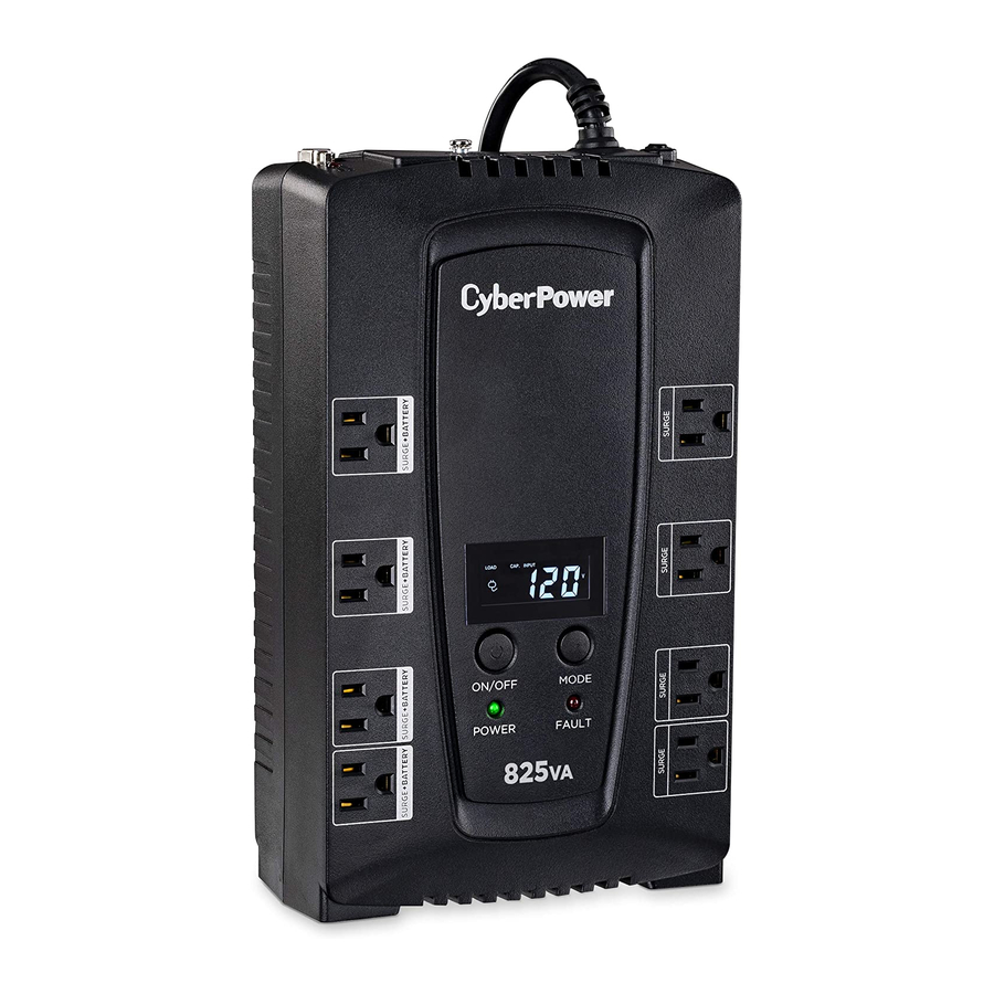
CP825LCD | CP600LCD
PRODUCT REGISTRATION
Thank you for selecting this CyberPower UPS product. This UPS is designed to provide unsurpassed power
protection, operation and performance during the lifetime of the product. Please take a few minutes to register
your product by visiting: CyberPowerSystems.com/registration. Registration certifies your product's warranty,
confirms your ownership in the event of a product loss or theft and entitles you to free technical support.
IMPORTANT SAFETY INSTRUCTIONS
(SAVE THESE INSTRUCTIONS)
This manual contains important safety instructions. Please read and follow all instructions carefully during
installation and operation of the unit. Read this manual thoroughly before attempting to unpack, install, or
operate your UPS.
CAUTION! To prevent the risk of fire or electric shock, install in a temperature and humidity controlled
indoor area free of conductive contaminants. (Please see specifications for acceptable temperature and
humidity range).
CAUTION! To reduce the risk of electric shock, do not remove the cover except to service the battery.
Turn off and unplug the unit before servicing the batteries. There are no user-serviceable parts inside
except for the battery.
CAUTION! Hazardous live parts inside can be energized by the battery even when the AC input
power is disconnected.
CAUTION! The UPS must be connected to an AC power outlet with fuse or circuit breaker protection.
Do not plug into an outlet that is not grounded. If you need to de-energize this equipment, turn off and
unplug the unit.
CAUTION! To avoid electric shock, turn off the unit and unplug it from the AC power source before
installing components.
CAUTION! Not for use in a computer room as defined in the Standard for the Protection of Electronic
Computer/Data Processing Equipment, ANSI/NFPA 75.
CAUTION! To reduce the risk of fire, connect only to a circuit provided with 20 amperes maximum branch
circuit over current protection in accordance with the National Electric Code, ANSI/NFPA 70.
DO NOT USE FOR MEDICAL OR LIFE SUPPORT EQUIPMENT! Under no circumstances should this unit be
used for medical applications involving life support equipment and/ or patient care.
DO NOT USE WITH OR NEAR AQUARIUMS! To reduce the risk of fire or electric shock, do not use with or
near an aquarium. Condensation from the aquarium can come in contact with metal electrical contacts
and cause equipment to short out.
DO NOT USE THE UPS ON ANY TRANSPORTATION! To reduce the risk of fire or electric shock, do not
use the unit on any transportation such as airplanes or ships. The effect of shock or vibration caused
during transit and the damp environment can cause the unit to short out.
INSTALLING YOUR UPS SYSTEM
UNPACKING
Inspect the UPS upon receipt, the box should contain the following: UPS unit, User manual, USB
A+B type cable and *PowerPanel® Personal Edition software is available as a free download at:
CyberPowerSystems.com/products/software.
OVERVIEW
The CP825LCD/CP600LCD provides complete power protection from utility power that is not always
consistent. The CP825LCD/CP600LCD features 1030 Joules of surge protection. The unit provides
long lasting battery backup during power outages with maintenance free batteries. The CP825LCD/
CP600LCD ensures consistent power to your computer system and includes software that will
automatically save your open files and shutdown your computer system during a utility power loss.
HOW TO DETERMINE THE POWER REQUIREMENTS OF YOUR EQUIPMENT
1. Ensure that the equipment plugged into the UPS does not exceed the UPS unit's rated capacity
(825VA/450W for CP825LCD, 600A/340W for CP600LCD). If the rated capacities of the unit are
exceeded, an overload condition may occur and cause the UPS unit to shut down or the circuit
breaker to trip.
2. There are many factors that can affect the amount of power that your electronic equipment will
require. For optimal system performance keep the load below 80% of the unit's rated capacity.
HARDWARE INSTALLATION GUIDE
1. Your new UPS may be used immediately upon receipt. However,
after receiving a new UPS, to ensure the battery's maximum
charge capacity, it is recommended that you charge the battery
for at least 8 hours. Your UPS is equipped with an auto-charge
feature. When the UPS is plugged into an AC outlet, the battery
will automatically charge whether the UPS is turned on or turned
off. Note: This UPS is designed with a safety feature to keep the
system from being turned on during shipment. The first time you
turn the UPS on, you will need to have it connected to AC power
or it will not power up.
2. With the UPS unit turned off and unplugged, connect your computer, monitor, and any other
peripherals requiring battery backup into the battery power supplied outlets. Plug the other peripheral
equipment (eg. printer, scanner, speakers, etc.) into the full-time surge protection outlets. DO NOT
plug a laser printer, paper shredder, copier, space heater, vacuum cleaner, sump pump, or other large
electrical device into the "Battery and Surge Protected Outlets". The power demands of these devices
will overload and possibly damage the unit.
3. Plug the UPS into a 2 pole, 3 wire grounded receptacle (wall outlet). Make sure the
wall branch outlet is protected by a fuse or circuit breaker and does not service
equipment with large electrical demands (e.g. air conditioner, refrigerator, copier,
etc.). The warranty prohibits the use of extension cords, outlet strips, and surge strips
in conjunction with the UPS unit.
4. Press the power switch to turn the unit on. The Power On indicator light will illuminate
green and the unit will "beep" once.
5. If an overload is detected, an audible alarm will sound and the unit will emit one long beep. To correct
this, turn the UPS off and unplug at least one piece of equipment from the battery power supplied
outlets. Make sure the circuit breaker is depressed and then turn the UPS on.
6. To maintain optimal battery charge, leave the UPS plugged into an AC outlet at all times.
7. To store the UPS for an extended period of time, cover it and store with the battery fully charged.
While in storage, recharge the battery every three months to ensure optimal battery life.
8. Ensure the wall outlet and UPS are located near the equipment being attached for proper accessibility.
BASIC OPERATION
1. Power Switch: Used as the master on/off switch for equipment connected to the battery power
supplied outlets. To turn the UPS ON, press the power button for approximately 2 seconds - you will
hear a constant tone (1 second) - and release after a short beep.
Alarm setting: The audible alarm can be turned Off or On by double click the POWER button. The
default setting is for the Alarm On. To turn the Alarm Off, double click the button. You will hear two
short beeps when the Alarm is turned off. To turn the Alarm back On, double click the button. You will
hear a single short beep when the Alarm is turned on. *When the Alarm is turned Off, there will be no
audible notification when the UPS reaches a low battery state.
2. Power On Indicator: This LED is illuminated when the utility power is normal
and the UPS outlets are providing power, free of surges and spikes.
3. Mode Switch: Press the Mode Switch for approximately 3 seconds to enter
setup mode to view options: Utility High/low Voltage range, sensitivity
setup, LCD sleep ON/OFF, battery test, buzzer ON/OFF, and low battery
alarm. When an option is selected, wait for 8 seconds for the setting to
be confirmed. After the setting has been confirmed the LCD screen will
leave setup mode and go back to status display. If there is no action for 8
seconds during setup, the LCD will also leave setup mode and go back to
the status display.
4. Fault Indicator: This LED is illuminated if there is a problem with the UPS
5. LCD module display: LCD display shows all the UPS information using
icons and messages. For more information please review the "Definitions
for Illuminated LCD Indicators" section.
6. Battery and Surge Protected Outlets: The unit has four battery powered
and surge protected outlets to ensure temporary uninterrupted operation
of your equipment during a power failure. (DO NOT plug a laser printer,
paper shredder, copier, space heater, vacuum cleaner, sump pump, or other
large electrical device into the "Battery and Surge Protected Outlets." The
power demands of these devices will overload and possibly damage the
unit.)
User's Manual
CP825LCD | CP600LCD
12
6
1
2
10
BASIC OPERATION CONT.
7. Full-Time Surge Protection Outlets: The unit has four surge suppression outlets. To turn the UPS OFF,
press the power button for approximately 2 seconds - you will hear a constant tone (1 second) - and
release after two short beeps.
8. USB Port: The USB port allows connection and communication between the USB port on the computer
and the UPS unit.
9. Serial Port: Serial Port allow for bi-directional communication among the UPS and the computer. The
UPS can control the computer's shutdown in case of an emergency, and at the same time, the computer
can monitor the UPS and alter its various programmable parameters.
10. Circuit Breaker & Reset: Located on the side of the UPS, the circuit breaker provides overload and fault
protection.
11. Ground Screw: The ground screw is used for any equipment that needs a chassis ground connection.
12. Outlets Designed for AC Adapters: The UPS unit has four widely-spaced outlets. AC power adapters
can be plugged into the UPS without overlapping or blocking adjacent outlets.
REPLACING THE BATTERY
Replacement of batteries located in an OPERATOR ACCESS AREA.
1. When replacing batteries, replace with the same number of the following battery:
CyberPower / RB1290 for CP825LCD; CyberPower / RB1270B for CP600LCD
2. CAUTION! Risk of Energy Hazard, 12V, maximum 9 Ampere-hour battery. Before replacing batteries,
remove conductive jewelry such as chains, wrist watches, and rings. High energy through conductive
materials could cause severe burns.
3. CAUTION! Do not dispose of batteries in a fire. The batteries may explode.
4. CAUTION! Do not open or mutilate batteries. Released material is harmful to the skin and eyes. It may be
toxic.
5. CAUTION: A battery can present a risk of electrical shock and high short circuit current. The following
precautions should be observed when working on batteries:
a, Remove watches rings, or other metal objects
b. Use tools with insulated handles.
CAUTION: risk of explosion if battery is replaced by an incorrect type. Dispose of used batteries
according to local regulations.
*In line mode, the AC input voltage may not stable all the time. To prevent the connected equipment
from damage caused by the unexpected voltage fluctuations, please adjust the sensitivity of the unit by
visiting: www.cyberpowersystems.com and download the LCD setup guide.*
TO REPLACE THE BATTERY
1. Turn off and unplug all connected equipment.
2. Unplug it from the AC power source.
3. Turn the UPS upside down.
4. Remove the 1 retaining screw.
5. Slide the battery compartment cover completely off of the unit.
6. Remove the battery from the compartment.
7. Disconnect the battery cables from the battery.
8. Install the replacement battery by connecting the red wire and black wire
to the positive (+) and negative (-) terminal of the battery.
9. Put the battery back into the compartment.
10. Slide back the battery compartment cover and tighten the retaining screw.
11. Charge the unit for 8 hours to fully charge the battery.
REMINDER: Batteries are considered HAZARDOUS WASTE and must be disposed of properly. Most
retailers that sell lead-acid batteries collects used batteries for recycling, as required by local regulations.
DEFINITIONS FOR LED INDICATORS & AUDIBLE ALARMS
POWER
FAULT
ALARM
On
Off
Off
Beep twice
On
Off
every 30
seconds
Rapid
beeping
On
Off
every
1/2 second
Flash once
On/Off
every 5
Constant tone
seconds
Flash twice
Off
every 5
Constant tone
seconds
Flash 3
On
times every
Constant tone
5 seconds
DEFINITIONS FOR ILLUMINATED LCD INDICATORS
INPUT voltage meter: This meter measures the AC voltage that the UPS system is receiving from the
utility wall outlet. The UPS is designed to continuously supply connected equipment with stable output
voltage. In the event of a complete power loss, severe brownout, or over-voltage, the UPS relies on its
internal battery to supply consistent 110/120 output voltage. The INPUT voltage meter can be used as a
diagnostic tool to identify poor-quality input power.
OUTPUT voltage meter: This meter measures, in real time, the AC voltage that the UPS system is
providing to the computer during normal AC/Utility Power mode, and battery backup mode.
ESTIMATED RUNTIME: This displays the run time estimate of the UPS with the
current battery capacity and load.
NORMAL icon: This icon appears when the UPS is working under normal
conditions.
BATTERY icon: During a severe brownout or blackout, this icon appears and
an alarm sounds (two short beeps followed by a pause) to indicate the UPS
is operating from its internal batteries. During a prolonged brownout or
blackout, the alarm will sound continuously to indicate the UPS's batteries
are nearly out of power. You should save files and turn off your equipment
immediately or allow the software to shut the system down.
OVER LOAD icon: This icon appears and an alarm sounds to indicate the
battery-supplied outlets are overloaded. To clear the overload, unplug some
of your equipment from the battery-supplied outlets until the icon turns off
and the alarm stops.
BATT. CAPACITY meter: This meter displays the approximate charge level of the UPS's internal battery in
20% increments. During a blackout or severe brownout, the UPS switches to battery power (the BATTERY
icon appears) and the battery charge level decreases.
LOAD CAPACITY meter: This meter displays the approximate output load level of the UPS battery outlets
in 20% increments.
12
SENSITIVITY meter: This meter displays the sensitivity level of the UPS. It is to control the sensitivity of
7
the UPS to switch to Battery Mode by selecting UPS shutdown voltage range. When the sensitivity is
5
increased, the UPS will switch to Battery Mode with less input power variation.
3
FAULT: The following number appears if there is a problem with the UPS. Press the POWER button to turn
4
the UPS off.
E22: Battery Mode or AC/Utility Power Mode Overload fault (Unplug at least one piece of equipment
from battery outlets and turn the UPS on again.)
E21: Battery Output Short fault (Unplug at least one piece of equipment from battery outlets and turn the
UPS on again.)
E01: Charger Fault (Contact CyberPower Systems for support)
11
9
E24: Internal Fault (Contact CyberPower Systems for support)
8
CONDITION
Normal
Utility Failure: The UPS is providing power to battery
power-supplied outlets from its battery.
Utility Failure: The UPS is providing battery power.
Rapid beeping indicates the unit will run out of power
soon.
Battery Mode or AC/Utility Power Mode Overload Fault:
Occurs when connected equipment exceeds the rating of
battery outlets of the unit. Please unplug at least one piece
of equipment from battery outlets.
Battery Output Short Fault: Please unplug at least one
piece of equipment from battery outlets and turn on the
UPS again. If the fault still exists, please contact Cyber-
Power Systems for support.
Charger Fault: Contact CyberPower for support.
LOAD BATT. CAP.
INPUT
100
The LCD display indicates a
variety of UPS operational
conditions. All descriptions
apply when the UPS is
plugged into an AC outlet
and turned on or when the
UPS is on battery.
OUTPUT
RUN_TIME
V
%
Min
Advertisement

Related Manuals for CyberPower CP825LCD


Summary of Contents for CyberPower CP825LCD
- Page 1 UPS and alter its various programmable parameters. Thank you for selecting this CyberPower UPS product. This UPS is designed to provide unsurpassed power 10. Circuit Breaker & Reset: Located on the side of the UPS, the circuit breaker provides overload and fault protection, operation and performance during the lifetime of the product.
- Page 2 Additional troubleshooting information can be found at: CyberPowerSystems.com/support/ 4. Pack and ship the CPS product to CyberPower and, if requested, the item(s) of Connected Equipment, a repair cost estimate for the damage to the Connected Equipment, and all claim forms that CyberPower provides to you.