
Related Manuals for JAR Systems MD-51 SP Series

Summary of Contents for JAR Systems MD-51 SP Series
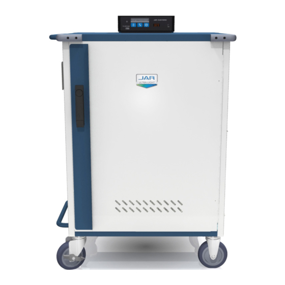
- Page 1 Ultra-Light Intelligent Service Plus Carts MD-51XX-SP MD-5150-SP MD-5135-SP Assembly and Configuration Manual Version D For a copy of the most up-to-date manual, please contact a JAR Systems representative or visit: www.JAR-Systems.com/Support...
- Page 2 Cart Assembly Instructions Components x42 or x32 (A1) x24 (B2) x16 (C3) x12 (D4) x12 1: Attach both side panels to the bottom of the cart. 2: Install the tray lid for the bottom shelf using one screw Misc. Position the studs in the side panel into the tabs in and one washer (A1) on each side.
- Page 3 6: Attach the gray rubber bumpers to each corner of the 7: Attach the rear center support to the top and bottom 8: OPTIONAL- If installing the charging cables at the cart’s top using 4 screws (B2) on each. The bumpers panels of the cart using 2 screws with 2 washers (A1) same time as the cart assembly, installing after step have a top and bottom side to them.
- Page 4 Cart Assembly Instructions 12: Align the openings on the bottom of the Intelligent 13: Find the plug end of the main power cable. Route 14: Route the 4 power strip cables through the hole in Charging System with the clips on the mounting it down the opening in the top of the cart and out the top of the cart.
- Page 5 18: Check the cart square by placing a rafter square in the 19: Secure the top of the cart using 4 nuts (C3). 20: If the charging cables were not installed in step bottom corner of the door frame or use the door as 8, install the cable management clips (G7, H8) a guide.
- Page 6 Installing Charging Cables and Adapters 1: Remove the security screw using the provided Torx key (F6) from the center of the shelf and temporarily 2: Determine the length of cable that is needed to reach place it in the side of the cart to hold the tray open during the wiring process.
- Page 7 In this case it may be best to arrange the majority of the adapters as far back in the tray as possible from left to right, flipping about half of them on their side. Please contact JAR Systems for additional assistance. EXAMPLE...
- Page 8 Installing Device Bays Service Plus carts feature adjustable device bays with multiple configuration options. This means that not every slot in the tray will have a divider in it and there may be extra, unused dividers at the end of the assembly process depending on which hole pattern is used.