Advertisement
Quick Links
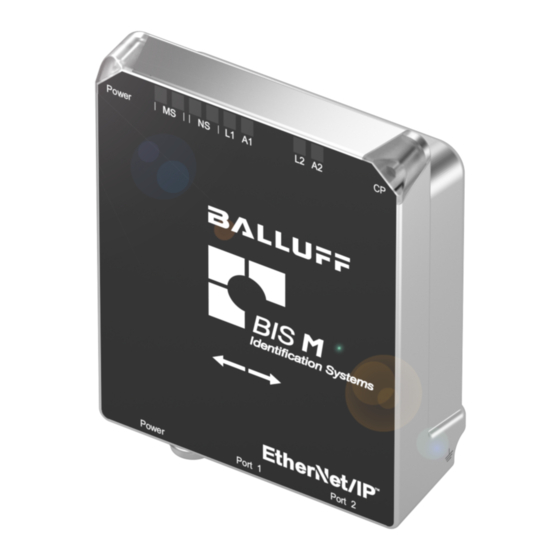
Balluff BIS M-4006-034-00x-ST4 EtherNet/IP
Montageanleitung / Installation Guide
BIS M-4006-034-001-ST4
BIS M-4006-034-002-ST4
Diese Montageanleitung ersetzt nicht die Bedienungsanleitung. Für eine
ordnungsgemäße Installation und Betrieb lesen Sie bitte die
Bedienungsanleitung und die dazugehörigen Sicherheitshinweise
sorgfältig durch.
Diese finden Sie zum Download unter http://www.balluff.de.
Bitte wenden Sie sich bei weiteren Fragen an unseren Kundenservice.
This Installation Guide does not replace the User´s Guide. For proper
installation and operation, please read the User´s Guide and the asso-
ciated safety instructions carefully.
This is ready for you to download at http://www.balluff.com.
For any further question please contact our Customer Service.
Modulübersicht / Module overview
TM
1
EtherNet/IP
Port 1
TM
2
EtherNet/IP
Port 2
3
Power IN
4
Status LEDs
5
Befestigungsbohrung/
Mounting hole
6
Aktive Fläche / Active surface
Mechanische Anbindung / Mechanical connections
Die Montage des Gerätes erfolgt über 4 Schrauben M5 an der Gerä-
terückseite. Alternativ kann das Gerät auch an der Steckerseite über
einen Montagewinkel mit 2 Schrauben M5 befestigt werden.
The device is mounted via 4 screws M5 on the back of the device.
Alternatively the device can also be mounted on the plug side via
mounting bracket with 2 screws M5.
Elektrische Verbindungen / Electrical connection
Erdung / Grounding
Erdung / Grounding
Die Verbindung des FE-Anschlusses vom Gehäuse zur Maschine
muss niederohmig sein und erfolgt über das mitgelieferte Er-
dungsband.
The FE connection from the housing to the machine must be low
impedance and via the included grounding band.
www.balluff.com
Rundantenne / Print-antenna
Stabantenne / Rod-antenna
6
TM
Spannungsversorgung / Power supply
Funktion /
Pin
Function
1
+24 V
2
n.c.
M12
A-coded
3
0 V
male
4
n.c.
TM
EtherNet/IP
Interface
Funktion /
Pin
Function
1
Tx+
2
Rx+
3
Tx-
M12
D-coded
4
Rx-
female
Nicht verwendete Buchsen müssen mit Blindkappen versehen
werden, damit die Schutzart IP 67 gewährleistet ist
Unused ports socket must be fitted with cover caps to ensure
IP 67 protection rating.
Funktionsanzeige / Function indicators
Status-Leds
Module status
LED
Status
aus /
Gerät nicht betriebsbereit /
off
Device is not ready for operation
grün /
Spannungsversorgung OK /
Power
green
Input power OK
grün blinkend/
Kabelbruch /
green flashing
Cable break
aus /
Kein Datenträger erkannt /
off
No data carrier detected
gelb /
Datenträger erkannt /
CP
yellow
Data carrier detected
gelb blinkend/
Datenträger wird bearbeitet /
yellow flashing
data carrier is being processed
aus / off
Gerät nicht eingeschaltet / Device not turned on
Gerät betriebsbereit / Device is ready for opera-
grün / green
tion
grün blinkend /
Stand-by: Gerät nicht konfiguriert / Stand-by:
green flashing
Device not configured
Schwerer nicht behebbarer Fehler / Severe, fatal
rot / red
MS
error
Einfacher behebbarer Fehler (z.B. eine fehler-
rot blinkend /
hafte Konfiguration) / Simple, non-fatal error
red flashing
(e.g. an incorrect configuration)
rot grün
Selbsttest: Gerät durchläuft nach dem Einschal-
blinkend / red
ten einen Selbsttest / Self test: Device is under-
green flashing
going a self test after being switched on
aus /
Gerät nicht eingeschaltet oder keine IP-Adresse/
off
Device not turned on or there is no IP address
Verbunden: Gerät hat eine bestehende Verbin-
grün / green
dung zum Master / Connected: Device has an
existing connection to the master
Keine Verbindung: Gerät hat keine bestehende
grün blinkend /
Verbindung oder IP-Adresse ist nicht vorhanden
green flashing
/ No connection: Device has no existing connec-
tion, IP address is not available
NS
Doppelte IP-Adresse: Gerät hat festgestellt, dass
seine IP Adresse schon verwendet wird / Doub-
rot / red
led IP address: Device identified that ist IP
address already being used
rot blinkend /
Verbindungs-Timeout / Connection timeout
red flashing
rot grün
Selbsttest: Gerät durchläuft nach dem Einschal-
blinkend / red
ten einen Selbsttest / Self-test: Device is under-
green flashing
going a self-test after being switched on
Beschreibung /
Description
Versorgung /
Power IN
GND /
GND
Beschreibung /
Description
Transmit Data +
Receive Data +
Transmit Data -
Receive Data -
Funktion / Function
1
Advertisement

Summary of Contents for Balluff BIS M-4006-034-00-ST4 Series
- Page 1 User´s Guide and the asso- male ciated safety instructions carefully. n.c. This is ready for you to download at http://www.balluff.com. For any further question please contact our Customer Service. Modulübersicht / Module overview EtherNet/IP...
- Page 2 Balluff Network Interface EtherNet/IP™ Betriebsbedingungen / Operating conditions aus / Keine Verbindung / Not connected Betriebstemperatur / L1 / 0 °C ... 70 °C Operating temperature grün / Verbindung / green Connected Lagertemperatur / -20 °C ... 85 °C Storage temperature...