Advertisement
Quick Links
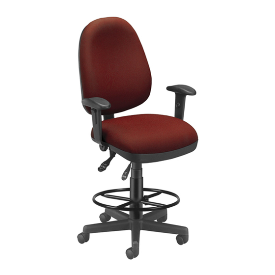
Model 122 / 122-DK
Parts Listing
A
B
6x25mm Screw
Large Washer
10 Units
4 Units
C
D
Small Washer
Telescopic Bellows
6 Units
1 Unit
E
F
Gas Lift
Seatback Bellows
1 Unit
1 Unit
G
H
Chair Back
Chair Seat
1 Unit
1 Unit
I
J
Chair Base
Chair Arms
1 Unit
2 Units
K
L
Casters
Seat Mechanism
5 Units
1 Unit
Computer Task Chair
G
D
L
B
A
E
I
WEIGHT CAPACITY: 250 lbs.
Assembly Notes:
During assembly, hand tighten screw only when all screws
are in place, you may then tighten all screws completely.
CAUTION:
1. Do not use this chair as a step ladder.
2. Check for loose screws and tighten them every 6 months.
Assembly Instructions
J
Tools Needed: Phillips Head Screwdriver
STOP
Please read all instructions before assembly.
Step 1: Insert Casters (K) into Chair Base (I).
If you are assembling a model with a DK Foot Ring please proceed
STOP
to subsequent pages for drafting kit assembly instructions.
Step 2: Insert Gas Lift (E) into Chair Base (I), and cover with
H
Telescopic Bellows (F).
Step 3: Place Chair Seat (H) upside down on flat surface, and
align holes in bottom of seat with four holes in Seat
C
Mechanism (L). Attach Seat Mechanism (L) using
6x25mm Screws (A) and Large Washers (B).
A
Tighten with screwdriver.
Step 4: Attach Chair Arms (J) to Chair Seat (H) using
6x25mm Screws (A) and Small Washers (C).
Tighten with screwdriver.
Step 5: Place Seatback Bellows (D) over attached bar on Chair
Back (G). Insert attached bar on Chair Back (G) into hole
F
in back of Seat Mechanism (L). Tighten the hand
tighten knob on the Seat Mechanism (L) until Chair
Back (G) is secure.
Step 6: Place Chair Seat (H) onto Chair Base (I) by inserting
top of Gas Lift (E) into the hole in the middle of the
Seat Mechanism (L). Push down on Chair Seat (H)
to secure to Chair Base (I).
K
03.30.2010
161 Tradition Trail Holly Springs, NC, 27540
800-520-7471 (voice)
919-362-4765 (fax)
www.ofminc.com
919- 303-6389 (voice)
support@ofminc.com
Advertisement

Related Manuals for OFM 122


Summary of Contents for OFM 122
- Page 1 Model 122 / 122-DK Computer Task Chair Parts Listing 6x25mm Screw Large Washer 10 Units 4 Units Assembly Instructions Tools Needed: Phillips Head Screwdriver STOP Please read all instructions before assembly. Step 1: Insert Casters (K) into Chair Base (I).
- Page 2 Model DK-2 Drafting Kit Assembly Parts Listing Circular Foot Rest Assembly Instructions 1 Unit STOP Please read all instructions before assembly. Prior to assembly, select only one Extension Tube for desired Height Chair Seat 9” Extension Tube will change seat height from 26.25”-30” 12”...