Table of Contents
Advertisement
Advertisement
Table of Contents

Related Manuals for US Robotics Courier V.34


Summary of Contents for US Robotics Courier V.34
- Page 1 COURIER HIGH SPEED MODEM Courier V.34 Dual Standard Fax USER MANUAL...
- Page 2 V.32/V.32 terbo, HST, V.FC, or V.34. Courier HST Dual Standard modems use any type of signaling, depending on the type of remote modem. V.34 modems can connect at rates up to 28.8K bps. Below is a brief description of the manual's contents.
- Page 3 COURIER HIGH SPEED MODEMS A NOTE ON COMMUNICATIONS SOFTWARE If you're using a computer rather than a terminal, you need communications software. Many brands are available, all of which are based on the modem's AT command set. Some users prefer their communications software to take control of the modem, and are more comfortable with a program that makes the modem almost transparent.
- Page 4 U.S. Robotics, the U.S. Robotics logo, and HST are registered trademarks of U.S. Robotics, Inc. Courier HST Dual Standard Fax, Courier V.32 terbo Fax, Total Control, and Adaptive Speed Leveling (ASL) are trademarks of U.S. Robotics, Inc. V.Fast Class and V.FC are trademarks of Rockwell International. Any trademarks, tradenames, service marks or service names owned or registered by any other company and used in this manual are the property of their respective companies.
-
Page 5: Table Of Contents
TABLE OF CONTENTS How to Use this Manual Table of Contents Limited Warranty FCC Registration Numbers IC (Industry Canada) Connecting to the Telephone Company Radio and Television Interference For Canadian Modem Users PART I. INSTALLATION AND OPERATION Chapter 1 Features and Compatibility Introduction Features Compatibility... - Page 6 COURIER HIGH SPEED MODEMS Reset the Jumpers Set DIP Switches Installing the Modem Testing the Installation Chapter 4 Data Mode Command Summary Command Set Usage Basic Commands Dialing/Answering Dialing Dial Options Cancel Dialing Store Phone Numbers Redialing Answer Mode Hanging Up Setting/Using Defaults Customizing NVRAM Resetting the Modem...
- Page 7 Percent Commands (%$) PART II. REFERENCE Appendix A Link Negotiation (Handshaking) and Error Control V.34 Handshaking V.Fast Class (V.FC) Handshaking U.S. Robotics V.32 terbo to U.S. Robotics V.32 terbo Other V. Protocol Operations Dual Standard Handshaking Error Control and Throughput V.42 Handshaking...
- Page 8 COURIER HIGH SPEED MODEMS Appendix C Alphabetical Command Summary Command Set Usage Basic Command Set Ampersand (&) Command Set Percent (%) Command Sets Appendix D Dial Security/Remote Access Dial Security Remote Access Appendix E Troubleshooting Appendix F Synchronous and Leased Line Operations Synchronous V.25 bis Online synchronous...
-
Page 9: Limited Warranty
COURIER HIGH SPEED MODEMS LIMITED WARRANTY U.S. Robotics, Inc., warrants to the original consumer or other end user purchaser that this product is free from defects in materials or workmanship for a period of two years from the date of purchase. During the warranty period, and upon proof of purchase, the product will be repaired or replaced (with the same or similar model) at our option, without charge for either parts or labor. -
Page 10: Ic (Industry Canada)
COURIER HIGH SPEED MODEMS FCC REGISTRATION FCC68: CJEUSA-73130-FA-E RINGER EQUIVALENCE: 0.4B FCC15: CJE-0263 (External modem) CJE-158-243 (Internal modem) CJE-0151-243 (Daughterboard) IC (INDUSTRY CANADA) This digital apparatus does not exceed the Class B limits for radio noise emissions from digital apparatus set out in the radio interference regulations of Industry Canada (formerly Canadian Department of Communications). -
Page 11: For Canadian Modem Users
15 of FCC rules, which are designed to provide reasonable protection against such interference in a residential installation. However, there is no guarantee that interference will not occur in a particular installation. If this device does cause interference to radio or television reception, which you can determine by monitoring reception when the modem is on and off, try to correct the problem with one or more of the following measures. - Page 12 COURIER HIGH SPEED MODEMS compliance with the above conditions may not prevent degradation of service in some situations. Repairs to certified equipment should be made by an authorized Canadian maintenance facility designated by the supplier. Any repairs or alterations made by a user to this equipment, or equipment malfunctions, may give the telecommunications company cause to request the user to disconnect the equipment.
-
Page 13: Chapter 1 Features And Compatibility
The following features and capabilities assure you of superior reliability and performance. Connections up to 28.8K bps With the V.34 standard and the V.Fast Class modulation scheme, two modems can connect at rates up to 28.8K bps, twice as fast as the rates of standard ITU-T (formerly CCITT) V.32 bis modems, which are limited to calls of 14.4K bps or less. - Page 14 COURIER HIGH SPEED MODEMS Universal Connect Courier high speed modems automatically detect and connect at the fastest available speed. Adaptive Speed Leveling (ASL) Like most high speed modems, Courier modems fall back to the next lower speed—for example, 19.2K, then 16.8K in V.terbo mode—if poor line conditions warrant.
- Page 15 Flow Control/Variable Serial Port Rates Flow control, required under error control, also allows the local serial port (DTE) rate to be set higher than the link (connection) rate, enabling greater efficiency and throughput. If your equipment and software support high rates, data can be sent from the computer to the modem at 115.2K, 57.6K, 38.4K or 19.2K bps, regardless of the link rate.
- Page 16 COURIER HIGH SPEED MODEMS Programmable Nonvolatile Memory You can tailor your own default settings and store them in non- volatile random access memory (NVRAM). Each time the Courier is powered on or reset, it operates at the settings you've specified. See Chapter 4, Appendix B, and Appendix C. Link Rate Negotiation The Courier automatically lowers its link rate to match a lower rate of a remote modem, in both Originate and Answer Modes,...
- Page 17 Modem Settings Displays On command, the modem displays its current settings, a handy way to check your transmission rate, S-Registers and other operational controls. The modem also displays the defaults stored in nonvolatile memory as well as its default configuration templates. See Chapter 6. HELP Screens The modem displays screens that summarize the command sets, Dial command options, and S-Register functions.
-
Page 18: Compatibility
COMPATIBILITY The Courier adheres to the following modulation schemes and standards, ensuring compatibility with a wide base of installed modems. Unless otherwise indicated, Dual Standard V.34 modems conform to the listed standards. NOTE: The International Telecommunication Union (ITU-T) was formerly the International Telegraph and Telephone Consultative Committee (CCITT). -
Page 19: Fax Standards
Levels 2, 3 and 4 error control, level 5 data compression, 1200 bps and higher ITU-T V.54 Analog, digital and remote digital loopback testing Fax Standards The Courier modem provides Group III-compatibility when combined with Class 1 or Class 2.0 fax software. In addition, the modem adheres to the following standards. -
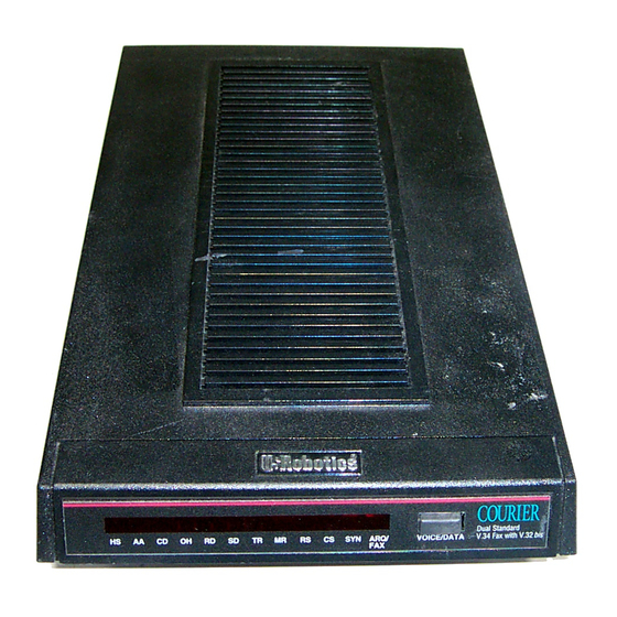
Page 20: Chapter 2 External Modem Set-Up
Figure 2.1—Courier V.34 Modem Reminder To prevent overheating, do not cover the vents on the top of the modem case. SWITCHES ON THE MODEM Voice/Data This push-button switch is used primarily to switch between voice and data communications during a call. Detailed instructions are in the Voice/Data Calls section in Appendix G. -
Page 21: Front Panel Indicators On The Modem
The modem has twelve status lights, or LEDs. See Appendix B for descriptions of their operations. PACKAGE COMPONENTS Your Courier modem package contains the following items: • The modem you purchased: Courier V.34 • An RJ11C phone cord • A power adapter •... -
Page 22: Communications Software
• If your machine has other than a 25- or 9-pin port, check your computer documentation or consult your dealer to find out what type of RS-232 connector is required. WARNING: If you're planning to use the high speed computer-to-modem rates of 115.K, 57.6K or 38.4K bps, follow the instructions concerning the RS-232 cable in Appendix B. -
Page 23: Refer To Appendix G
COURIER HIGH SPEED MODEMS Refer to Appendix G..if your modem is installed in a Hewlett Packard system that uses the Ack/Enq communications protocol. INSTALLING THE MODEM 1. Turn off the computer or terminal and its peripheral devices. - Page 24 COURIER HIGH SPEED MODEMS NOTE: If you have built your own RS-232 cable and it does not support the Data Terminal Ready (DTR) signal, set DIP switch 1 ON, for DTR override. The override causes the modem to operate as if the DTR signal were always ON, and enables the modem to accept commands.
-
Page 25: Testing The Installation
COURIER HIGH SPEED MODEMS TESTING THE INSTALLATION Use the following procedures to verify that your modem is working properly. 1. Turn on your computer or terminal. Then turn the Courier's power switch ON. The following front panel indicators, or LEDs, will light up on the modem. CD Carrier Detect, if you have set DIP switch 6 ON, enabling the CD override Data Terminal Ready, if you have set DIP switch 1... - Page 26 COURIER HIGH SPEED MODEMS Troubleshooting If your entered command is not displayed, your local echo is OFF. To turn the local echo ON, send the modem the following command: ATE1 <Enter> If double characters appear on the screen, both your modem and software are set to local echo ON.
- Page 27 COURIER HIGH SPEED MODEMS 5. As a final check, make sure the modem gets a dial tone. Type the following Dial command: ATD <Enter> On receipt of the command, the modem goes off hook and waits for a dial tone. The OH indicator lights up, and you'll hear the dial tone from the modem's speaker.
-
Page 28: Chapter 3 Internal Modem Setup
CHAPTER 3. INTERNAL MODEM SET UP PACKAGE COMPONENTS Your Courier modem package contains the following items: • The modem you purchased: Courier V.34 • An RJ11C phone cord • A power adapter • Fax software and manual • A Quick-Reference card WHAT YOU NEED The Courier modem has minimal operational requirements. -
Page 29: A Telephone Adapter
COURIER HIGH SPEED MODEMS A Telephone Adapter..if you have an older telephone installation that does not have the appropriate modular wall jack and plug. Adapters and RJ11C connectors are available from your telephone company or computer dealer. YOU SHOULD. -
Page 30: Select A Serial Port
COURIER HIGH SPEED MODEMS If you're only using COM1 for a device, you can skip this sec- tion except for DIP Switches, just before Installing the Modem. If you've already installed devices at both COM1 and COM2, you will have to select either COM3 or COM4. Carefully review the following section for complete instructions. -
Page 31: Select An Interrupt Request (Irq)
COURIER HIGH SPEED MODEMS Select an Interrupt Request (IRQ) IBM-compatible computers reserve IRQ4 for COM1 and IRQ3 for COM2, as shown below. Some communication programs support reserved IRQs for two serial ports. Serial Port COM1 IRQ4 COM2 IRQ3 COM3 IRQ4* COM4 IRQ3* *Select IRQ4 (COM3) or IRQ3 (COM4) -
Page 32: Reset The Jumpers
COURIER HIGH SPEED MODEMS Reset the Jumpers Figure 3.1 shows an enlarged view of the modem's jumper switches. If you hold the modem so that the rear panel is at the bottom and the edge connector is at the left of the circuit board you can locate the COM and IRQ jumpers near the center left side of the board. -
Page 33: Set Dip Switches
COURIER HIGH SPEED MODEMS Set DIP Switches A ten-position bank of Dual In-Line Package (DIP) switches is located at the rear of the modem. A summary of the DIP switch functions and options is in Appendix B in this manual and on the Quick Reference Card. - Page 34 COURIER HIGH SPEED MODEMS 3. Unscrew the solid bracket at the back of any available standard half-card slot.) The bracket will pop out of the back, leaving an opening in DIP switches. and a 2-inch groove. These grooves are lined on both sides with metal guides.
-
Page 35: Testing The Installation
COURIER HIGH SPEED MODEMS 7. If you currently have a phone plugged into the wall jack, disconnect it. Plug one end of the phone cable that came with the modem into the TELCO jack at the rear of the modem. This allows the modem to switch into the tele- phone network, get a dial tone, and so on. - Page 36 COURIER HIGH SPEED MODEMS 3. Perform the function that lets you send AT commands to the modem, that is, puts the computer in Terminal mode. Some communications programs do this automatically upon loading. Others require you to display a communications or terminal screen, type a Function key, or perform some other operation.
- Page 37 COURIER HIGH SPEED MODEMS Make sure your software has put the computer in Terminal mode, so that you can send the modem commands. Then review Step 4, on the previous page. d. Be sure that DIP switches 1 and 6 are set ON or OFF according to your terminal or software requirements.
-
Page 38: Command Set Usage
CHAPTER 4. DATA MODE OPERATIONS The information in this chapter applies to asynchronous calls only. For synchronous operations, refer to Appendix F. Detailed command descriptions are in this chapter. Additional command summaries are in Appendix C, on the bottom panel of the modem, and in the Quick-Reference Card. -
Page 39: Basic Commands
COURIER HIGH SPEED MODEMS 3. All commands except A/, A> and +++ are preceded by the AT (attention) prefix and are executed with the Enter/Carriage Return key (<Enter>). 4. Command length = 60 characters maximum. The modem doesn't count the AT prefix, Carriage Return character, or spaces. - Page 40 • Configuration: Echo/Speaker Result Codes Modulation Error Control/Data Compression Data Rates RS-232 Signal Operations Flow Control • S-Registers • Inquiry and Help • Testing • International Calls • Miscellaneous Commands For an alphabetical listing of commands, check the first page of the index.
- Page 41 COURIER HIGH SPEED MODEMS DIALING/ANSWERING Dial the specified phone number; also execute Dial options. The maximum number of characters allowed is 60, including the AT prefix, punctuation and spaces. The Carriage Return (Enter key) isn't counted as a character. NOTE: With the exception of the following Dial options, the modem ignores any commands issued after D in the same command string.
- Page 42 COURIER HIGH SPEED MODEMS " Dial the letters that follow (in an alphabetical phone number). NOTE: If you are including another command after the dial string, use closing quotation marks before the additional command. Transfer a call (flash the switch-hook). This command applies to modems in installations where other modems share the phone line.
- Page 43 COURIER HIGH SPEED MODEMS Reverse frequencies. This command allows calls to an originate-only modem. It reverses the modem's originate/answer frequencies, forcing the Courier to dial out at the answer frequency. The command follows the Dial command, before or after the phone number: AT D1234567R <Enter>...
-
Page 44: Store Phone Numbers
Store Phone Numbers This command stores up to ten numbers, where n is the position &Zn=s 0 9 in nonvolatile memory, and s is the phone number string. The number-string may be up to 40 characters long, including any Dial command options. AT &Z2=555-6789 <Enter>... -
Page 45: Answer Mode
COURIER HIGH SPEED MODEMS The cycle continues until the modems connect or the modem reaches a maximum of 10 attempts. The 10-try limit is mandated by Industry Canada (IC) to prevent tying up local telephone company exchanges with unconnected calls. A>... -
Page 46: Hanging Up
When the modem senses a call coming in, it sends the result code RING to your screen, goes off hook, and sends the remote modem a high-pitched answer tone. If there is no Carrier Detect within 60 seconds, the modem hangs up. If the connection is made, the modem sends a CONNECT result code. - Page 47 COURIER HIGH SPEED MODEMS Escape code operations. Once the modem is online to another system, the only command it recognizes is an escape code of three typed pluses, which forces the modem back to Command mode. Do the following when issuing the command: •...
-
Page 48: Setting/Using Defaults
Returning Online If DIP switch 9 is ON (on detection of the escape code the modem maintains the connection), you can issue commands and then toggle the modem back online with the On command, as in this example: AT Q1 O <Enter> There are two ways to return online. -
Page 49: Customizing Nvram
COURIER HIGH SPEED MODEMS When you power on the Courier, it loads the settings stored in NVRAM if DIP switch 10 is OFF. Until you write your own settings to NVRAM, the defaults stored there are the same as the permanent ROM factory settings stored in position 1, &F1. To view the &F1 settings, select option 5 of the I (inquiry) command: AT I5 <Enter>... -
Page 50: Resetting The Modem
Resetting the Modem Software reset to NVRAM settings when DIP switch 10 is OFF (factory setting). If DIP switch 10 is OFF, the modem resets to the &F0 configuration template, with no flow control. NOTE: Use the ATZ command also if you've changed the position of DIP switches 1 7 or 9 while the modem is on, so that the modem can read the new setting. -
Page 51: Result Codes
COURIER HIGH SPEED MODEMS In some microcomputer documentation, the term duplex is applied to local online echoing, although the term is not techni- cally accurate. Online echo ON. Sometimes called half duplex. As the modem transmits data to a remote system, it also sends a copy of the data to the screen. - Page 52 COURIER HIGH SPEED MODEMS Result code set options. Use the following table (Default = X7, all codes except 12/VOICE). For result codes for synchronous operations, see Appendix F. Setting Result Codes X0 X1 X2 X3 X4 X5 X6 X7 0/OK 1/CONNECT 2/RING 3/NO CARRIER...
- Page 53 COURIER HIGH SPEED MODEMS Result Code Meaning 0/OK Command has been executed. 1/CONNECT Connection with another modem; if set to X0, connection may be between 300 and 28.8 bps; if X1 or higher, connection is at 300 bps. 2/RING Incoming ring detected. 3/NO CARRIER Carrier detect has failed or carrier has been dropped due to disconnect.
- Page 54 Additional Result Code Subsets NOTE: ARQ (Automatic Repeat Request) is used in this manual to denote calls under error control. &An Enable/disable additional result code subsets. See the Xn command earlier in this chapter. &A0 ARQ result codes are disabled. This setting does not affect an error control connection;...
- Page 55 COURIER HIGH SPEED MODEMS 93/CONNECT 21600/V32 97/CONNECT 21600/VFC 101/CONNECT 24000/VFC 105/CONNECT 26400/VFC 109/CONNECT 28800/VFC 139/CONNECT 14400/VFC 143/CONNECT 16800/VFC 147/CONNECT 19200/VFC 111/CONNECT 21600/V34 113/CONNECT 24000/V34 115/CONNECT 26400/V34 117/CONNECT 28800/V34 120/CONNECT 2400/V34 124/CONNECT 4800/V34 128/CONNECT 7200/V34 132/CONNECT 9600/V34 136/CONNECT 12000/V34 140/CONNECT 14400/V34 144/CONNECT 16800/V34 148/CONNECT 19200/V34 &A3 Additional error control indicator (LAPM, HST, MNP,...
-
Page 56: Modulation
Handshake options. There are three commands that apply to international calls above 1200 bps Bn, &Gn, &Pn. See International Calls later in this chapter for information on the other two settings. ITU-T (formerly CCITT) answer sequence. Default. This is required to answer all V.32-type calls, as well as calls from overseas. - Page 57 COURIER HIGH SPEED MODEMS &M6 The modem enters V.25 bis synchronous mode, using a character-oriented link protocol similar to BISYNC. See Appendix F for more information &M7 The modem enters V.25 bis synchronous mode, using the HDLC link protocol. &Kn Enable/disable data compression.
-
Page 58: Data Rates
The modem can be set to a fixed or variable serial port rate. A fixed rate sets the modem for the highest possible throughput and provides the best performance. A variable rate allows the modem to switch to match the more limited rate on the phone connection. - Page 59 COURIER HIGH SPEED MODEMS &B2 Fixed for ARQ calls/Variable for non-ARQ calls. Answer mode only. When the modem goes off hook and connects in ARQ mode, it shifts its serial port rate up to a user-specified rate, for example, 38.4K bps. If the connection is not under error control, the modem behaves as if it were set to &B0 and switches its serial port rate to match the connection rate of each call.
-
Page 60: Rs-232 Signal Operations
&N10 19.2K bps (terbo, V.FC, and V.34 only) &N11 21.6K bps (terbo, V.FC, and V.34 only) &N12 24K bps (V.FC and V.34 only) &N13 26.4K bps (V.FC and V.34 only) &N14 28.8K bps (V.FC and V.34 only) Data Mode Operations... -
Page 61: Flow Control
COURIER HIGH SPEED MODEMS Return online with the On command, or hang up with the Hn command. &D2 Normal DTR operations. The terminal or computer must send a DTR signal for the modem to accept commands. Dropping DTR terminates a call. &Sn The modem sends the computer or terminal a Data Set Ready (DSR) signal via the RS-232 interface. - Page 62 Hardware Control The modem drops the Clear to Send (CTS) signal it's been sending to the computer or terminal when the modem's buffer nears 90% capacity. It starts sending CTS again when the buffer is about half full. Software Control The modem sends the computer or terminal the standard ASCII Transmit OFF (XOFF) character, <Ctrl>-S, when its buffer nears 90% capacity.
- Page 63 COURIER HIGH SPEED MODEMS Transmit Data Buffer Sizes The Transmit Data refers to the data from the computer, which the modem is to transmit over the phone line. The size of the Transmit data buffer depends on whether the connection is under error control or not, as follows. •...
- Page 64 &H3 Use both hardware and software flow control. If you are unsure about what your equipment supports, select this option. But keep the warning, above, in mind about software flow control. Received Data Flow Control Separate commands, &Rn (hardware) and &In (software), con- trol the flow of Received Data passed by the Courier to your computer or terminal.
- Page 65 COURIER HIGH SPEED MODEMS NOTE: Because of the risk described in the above warning, the settings that follow are only recommended for users whose data does not include XON/XOFF control characters. &I1 The Courier acts on your typed XON/XOFF commands, <Ctrl>-S or <Ctrl>-Q, and passes them to the remote computer.
-
Page 66: S-Registers
In non-ARQ mode, a Courier set to &I5 operates as though flow control were disabled (&I0); it does not look for your typed XON/XOFF commands. However, it looks for XON/XOFF characters coming in over the phone link. When the remote operator sends XON/XOFF com- mands, the Courier either resumes or stops transmitting data over the link and drops the characters from the data stream. -
Page 67: Inquiry And Help
COURIER HIGH SPEED MODEMS INQUIRY AND HELP The modem displays information such as the current modem settings, product code, and call duration. It also displays summary information for every command that the modem supports. For more information on Inquiry and Help commands, including sample displays, see Chapter 6. -
Page 68: Miscellaneous Commands
&Pn This command sets the ratio of the off-hook/on-hook (make/ break) interval for pulse dialing. The default sets the modem for use in North America. The ratio must be changed if the modem is used in the United Kingdom and some Common- wealth countries. - Page 69 COURIER HIGH SPEED MODEMS &ZC=s Write the following command string s to NVRAM. The command string may be up to 30 characters long; spaces are not counted. This command can be used so that you can call another modem without loading your communications software.
-
Page 70: Chapter 5 Fax Operations And Call Detection
CHAPTER 5. FAX OPERATIONS AND CALL DETECTION FAX OPERATIONS Compatibility The Courier modem provides Group III-compatibility when combined with Class 1 or Class 2.0 fax software. In addition, the modem adheres to the following standards. NOTE: The International Telecommunication Union (ITU-T) was formerly the International Telegraph and Telephone Consultative Committee (CCITT). -
Page 71: Fax Operations
COURIER HIGH SPEED MODEMS If you have a problem, however, and think the modem may be in the wrong mode, you can use one of the following AT commands to manually switch the modem: AT+FCLASS=0 (Switch to Data mode) <Enter> AT+FCLASS=1 (Switch to Class 1 Fax mode) <Enter>... -
Page 72: Notes To Programmers
FCC Notice FCC part 68, rules regarding fax operation, has been amended as follows: Telephone facsimile machines—identification of the sender of the message: It shall be unlawful for any person within the United States to use a computer or other electronic device to send any message via a telephone facsimile machine unless such a message clearly contains, in a margin at the top or bottom of each transmitted page or on the first... -
Page 73: Call Detection
COURIER HIGH SPEED MODEMS CALL DETECTION Courier High Speed modems support Call Detection, which is a method of reporting whether an incoming call is Data, Fax Class 1, or Fax Class 2.0. It is especially useful for Bulletin Board systems, as it automates recognition of different calls from multiple users. -
Page 74: Chapter 6 Queries And Help Screens
CHAPTER 6. QUERIES AND HELP SCREENS USER INQUIRIES (In) The Inquiry command has 11 options. The most commonly used options display the following information: ATI3 Call duration ATI4 Current settings ATI5 NVRAM settings ATI6 Link diagnostics summary I0 The modem returns a 4-digit product code. If you have a problem and call U.S. - Page 75 If your modem connects to a modem that has Dial Security and local access enabled, you cannot view the stored phone numbers. ati5 USRobotics Courier Dual Standard V.34 Fax NVRAM Settings... DIAL=PULSE B0 F1 M1 X7 BAUD=57600 PARITY=N WORDLEN=8 &A3 &B1 &G0 &H1 &I0 &K3 &L0 &M4 &N0 &P0 &R2 &S0 &T5 &X0 &Y1 %N6...
- Page 76 The duration of the last call or real time is displayed depending on the Kn setting. ati6 USRobotics Courier Dual Standard V.34 Fax Link Diagnostics... Chars sent Chars Received Chars lost...
- Page 77 COURIER HIGH SPEED MODEMS Link Timeouts: Protocol detection problems: communications were severed momentarily, and the modems probably recovered. This does not indicate the retry timeout. Link Naks: Negative acknowledgments (one or more blocks). Data Compression: Indicates the type of data compression negotiated for the call (V42BIS or MNP5) or NONE.
- Page 78 COURIER HIGH SPEED MODEMS GSTN (General Switch Telephone Network) Clear Down: The connection was non-ARQ and DTR was dropped from one side of the connection, or the DISC frame was corrupted due to noise. Illegal Command Code: The modem received an invalid V.42 bis (compression) frame.
- Page 79 COURIER HIGH SPEED MODEMS Unable to Retrain: After several attempts, disturbances on the phone line prevented the modems from retraining, and they could no longer transmit or receive data. XID Timeout: The modems failed to negotiate the V.42 Detection (XID Exchange) phase. Dial Security Disconnect Reason: Possible reasons the answering modem may have hung up during a Dial Security session are as follows:...
-
Page 80: S-Register Query (Sr?)
I10 View Dial Security Account status. For security administrators only, unless local security is disabled, S53=0 or S53.2=0. ati10 USRobotics Courier Dual Standard V.34 Fax DIAL SECURITY ENABLED:[N] PROMPTING ENABLED:[N] LOCAL ACCESS PASSWORD:[NO PSW] ACCOUNT PSW ACCT/E [NO PSW] [NO PSW]... -
Page 81: Stored Command String Query (&Zc?)
COURIER HIGH SPEED MODEMS LAST-DIALED NUMBER QUERY (DL?) At this command the modem displays the number stored in the last-dialed number buffer: ATDL? <Enter> STORED COMMAND STRING QUERY (&ZC?) At this command the modem displays the command string stored in NVRAM with the &ZC=s command: AT&ZC? <Enter>... -
Page 82: Extended Command Set (&$)
HELP, Command Quick Reference (CTRL-S to Stop, CTRL-C to Cancel) &$ HELP, Ampersand Commands HELP, Percent Commands Repeat Last Command A> Continuously Repeat Command Command Mode Prefix Answer Call n=0 V.32 originate mode n=1 HST originate mode n=0 Transmitter Off n=1 Transmitter On Dial a Telephone Number n=0..9#*TPR,;"W@!()-... -
Page 83: Dialing (D$)
COURIER HIGH SPEED MODEMS Dialing (D$) At ATD$, the Courier displays this Dial command summary: atd$ HELP, Dial Commands (CTRL-S to Stop, CTRL-C to Cancel) 0-9 Digits to Dial Auxiliary Tone Dial Digit Auxiliary Tone Dial Digit Tone Dialing Pulse Dialing Call an Originate Only Modem Pause (Wait for S8 Time) Remain in Command Mode After Dialing... -
Page 84: Percent Commands (%$)
Percent Commands (%$) At AT%$, the Courier displays a screen that shows a partial summary of the percent command functions. A second screen, activated by pressing any key, shows the remaining registers. The first screen is as follows. at%$ HELP, Percent Commands (CTRL-S to Stop, CTRL-C to Cancel) %An= Security Account Information %Fn Command Structure %An= PW,ACCT E,DIAL B,NEW#,PH#... -
Page 85: Appendix A Link Negotiation (Handshaking) And Error Control
V.34 HANDSHAKING The Courier defaults to V.34 and tries for the highest possible speed when it attempts to connect with another modem, 28.8K bps. The entire V.FC range comprises 28.8K, 26.4K, 24K, 21.6K, 19.2K, 16.8K, 14.4K, 9600, 7200, 4800, and 2400 bps. -
Page 86: V.fast Class (V.fc) Handshaking
COURIER HIGH SPEED MODEMS If the remote modem has V.34 capability, the two modems use a line probing technique to determine the highest speed possible under current line conditions, and complete the connection. If the remote modem does not have V.34 capability, a calling... -
Page 87: Other V. Protocol Operations
OTHER V. PROTOCOL OPERATIONS Earlier, lower-speed V. protocols do not employ line probing. Instead they use predefined answer tones to specify, or identify, speed capabilities. These protocols define the following maximum speeds. V.32 terbo: 19.2K bps, with an additional Courier-to- Courier speed of 21.6K bps. -
Page 88: Dual Standard Handshaking
COURIER HIGH SPEED MODEMS Dual Standard Handshaking We recommend that Dual Standard modems be set to retain the default B0 and &N0 settings. This allows them to connect with V. protocol modems and HST modems in both Originate and Answer modes at a variety of speeds. An originating Dual Standard modem set to B1 sends out a Bell answer tone, which is the prevalent standard in the U.S. -
Page 89: V.42 Handshaking
V.42 Handshaking This international standard includes a two-stage handshaking process: • A Detection phase that is based on an exchange of predefined characters. • LAPM (Link Access Procedures for Modems) Negoti- ation. In this phase, the modems identify their capabilities concerning maximum data block size and the number of outstanding data blocks allowed before an acknowledgment is required. -
Page 90: Flow Control
COURIER HIGH SPEED MODEMS Possible sizes are as follows: Bits Entries 1024 2048 U.S. Robotics modems use 11-bit, or 2048-entry dictionary, but drop down if the remote modem uses a 9- or 10- bit dictionary. The size of the dictionary for a call is reported in the ATI6 display. -
Page 91: Throughput Guidelines
Throughput Guidelines The following guidelines should help to make the most of the modem's advanced performance features. In many instances, experimentation and experience will indicate what works best for your applications. 1. Optimal throughput is attained under the following conditions: •... -
Page 92: Typical Throughput
Line conditions and data rate affect throughput. Also remember, your serial port rate must match or exceed your connection rate. If you set your serial port rate at 19.2K bps, the V.34 modem will only connect at or below 19.2K bps. Link Negotiation and Error Control... - Page 93 The tables below indicate the typical throughput, in characters per second (cps), that can be expected under the following conditions. • Connection (link) rates of 14.4K, 21.6K, and 28.8K bps, respectively • Serial port rates set at 57.6K bps for the 14.4K bps connection and 115.2K bps for the 21.6K and 28.8K bps connections •...
- Page 94 COURIER HIGH SPEED MODEMS 28.8K bps File Type Text file .ZIP files Database files Graphic files A-10 Link Negotiation and Error Control Typical throughput (cps) 6800 3200 9600 5800...
-
Page 95: Appendix B Summaries And Tables
COURIER HIGH SPEED MODEMS APPENDIX B. SUMMARIES AND TABLES CONTENTS The RS-232 Interface, with Pin Definitions Front Panel Indicators DIP Switch Summary Default Settings S-Register Summary ASCII Chart Summaries and Tables... -
Page 96: The Rs-232 Interface
COURIER HIGH SPEED MODEMS THE RS-232 INTERFACE DESCRIPTION The RS-232 interface is a standard developed by the Electronic Industries Association (EIA). It defines the signals and voltages used when data is exchanged between a computer or terminal and a modem or serial printer. Data is transmitted between the devices via a cable with 25-pin, 9-pin, 8-pin or custom-built connectors. - Page 97 PIN ASSIGNMENTS The entire standard covers many more functions than are used in most data communications applications. Pin assignments are factory set in the Courier to match the standard DB-25 assign- ments in the following table. DB-9 connectors for AT- compatible computers should be wired at the computer end of the cable as shown in the DB-9 column.
- Page 98 COURIER HIGH SPEED MODEMS Minimum Requirements Some computer/terminal equipment supports only a few of the RS-232 signal functions set in the Courier. The minimum required for the modem to operate are as follows: Asynchronous Calls DB-25 DB-9 Required only if you have the Data Terminal Ready Operations switch OFF (DIP switch 1 OFF).
-
Page 99: Front Panel Indicators
If you decide to build your own cable, use a low-capacitance cable. To further minimize the capacitance, connect only those functions (pins) that your application requires. FRONT PANEL INDICATORS Symbol Meaning Status High Speed All calls above 2400 bps: ON during call progress, after completion of dialing;... - Page 100 COURIER HIGH SPEED MODEMS Symbol Meaning Status MR Modem Ready/ ON when the Courier is powered on. Test Mode Flashes when the modems retrain, including online fallback, or while the modem is in Test mode. Request to ON if your terminal or software supports RTS Send and sends the RTS signal.
-
Page 101: Dip Switch Summary
DIP SWITCH SUMMARY PURPOSE The DIP switches, located at the rear of the modem, are for adapting the modem to your equipment and personal require- ments. If necessary, review your software documentation. Some users are able to move a single switch with a finger tip. If this doesn't work for you, use a toothpick or other small instrument. - Page 102 COURIER HIGH SPEED MODEMS Factory Switch Setting Function Result Code Display OFF Results suppressed ON Results enabled Command Mode Local Echo OFF Keyboard commands displayed ON Echo suppressed Auto Answer OFF Modem answers on first ring ON Auto answer disabled Carrier Detect Operations OFF Courier sends CD signal when it connects ON CD always ON (Override)
-
Page 103: Default Settings
DEFAULT SETTINGS USER-PROGRAMMABLE DEFAULTS You can create your own default configuration and store it in nonvolatile random access memory (NVRAM) using the &W command described in Chapter 4. As long as DIP switch 10 is OFF when you power on the modem, your defaults are loaded into the modem's random access memory (RAM). -
Page 104: F1 Hardware Flow Control (Default
COURIER HIGH SPEED MODEMS Table B.3 &F1 Hardware Flow Control Default Template NVRAM Options Handshake option Error control/sync Data compression Transmit data hardware Rec'd data hardware flow control Rec'd data software flow control Serial port rate select Link rate select Result code subset Protocol response codes Tone/Pulse dialing... -
Page 105: F2 Software Flow Control
The &F2 and &F3 factory setting templates are similar to the &F1, with the exception of the commands which are highlighted in bold in tables B.4 and B.5. Table B.4 &F2 Software Flow Control Template NVRAM Options Handshake option Normal/error control/sync Data compression Transmit data flow control Rec'd data hardware flow control... -
Page 106: F3 Hst Cellular
COURIER HIGH SPEED MODEMS Table B.5 &F3 HST Cellular Template NVRAM Options Handshake option Normal/error control/sync Data compression Transmit data flow control Rec'd data hardware flow control Rec'd data software flow control Serial port rate select Link rate select Result code subset Protocol response codes Tone/Pulse dialing Online local echo... -
Page 107: F0 No Flow Control
If DIP switch 10 is ON when the modem is powered on, or you load factory template 0 (&F0), the following settings take effect. The differences between factory template 0 (&F0) and factory template 1 (&F1) are noted in bold. Table B.6 &F0 No Flow Control Low PerformanceTemplate NVRAM Options... - Page 108 COURIER HIGH SPEED MODEMS Table B.7 NVRAM S-Register Options Auto Answer Escape code character Carriage Return character Line Feed character Backspace character Dial wait-time, sec. Carrier wait-time, sec. Dial pause, sec. Carrier Detect time, 1/10th sec. S10 Carrier loss wait-time, 1/10th sec. S11 Tone duration, spacing, msec.
-
Page 109: S-Register Summary
S-REGISTER SUMMARY USAGE The default values are those users typically require. Change the settings of an S-Register with the ATSr=n command, where r is the register and n is a decimal value from 0-255: ATS13=8 <Enter> The modem does not perform a value-range check. Some values you select may not work with some equipment, and you'll have to readjust the settings. - Page 110 COURIER HIGH SPEED MODEMS Register Default See DIP Switch 5 B-16 Summaries and Tables Function Sets the number of rings on which to answer when in Auto Answer mode. S0=0 disables Auto Answer, the same as DIP switch 5 ON (factory setting). S0=1 enables Auto Answer and the modem answers on the first ring.
- Page 111 Register Default Function Sets the duration, in seconds, for the pause (,) option in the Dial command and the pause between command re-executions (> and A> commands). Sets the required duration, in tenths of a second, of the remote modem's carrier signal before recognition by the Courier.
- Page 112 COURIER HIGH SPEED MODEMS Register Default B-18 Summaries and Tables Function Bit-mapped register. Select the bit(s) you want on and set S13 to the total of the values in the Value column. For example, ATS13=20 enables bit 2 (value = 4) and bit 4 (value = 16).
- Page 113 Register Default Function Bit-mapped register. To set the register, see the instructions for S13. Bit Value Result * The default 1.5K byte non-ARQ buffer allows data transfer with X- and Ymodem-type file transfer protocols without using flow control. The 128-byte option allows remote users with slower modems to stop data you're transmitting from scrolling off their screens.
- Page 114 COURIER HIGH SPEED MODEMS Register Default B-20 Summaries and Tables Function Bit-mapped test register. To set the register, see the instructions for S13. For information on testing, see Appendix H. Bit Value Result Analog Loopback Dial test Test pattern Remote Digital Loopback Reserved Reserved Reserved...
- Page 115 Register Default Function Sets the duration, in 20-millisecond units, between pulsed DSR signals when the modem is set to &S2 or &S3. The default is 3 seconds. Sets DTR recognition time in 1/100th of a second units. Sets the duration, in 1/100th of a second units, of the delay between RTS and the modem's CTS response in synchronous mode.
- Page 116 COURIER HIGH SPEED MODEMS Register Default B-22 Summaries and Tables Function 128 Unusual software incompati- bility. Some software may not accept 7200, 12000, 14400, 16800, 19200 and 21600 bps result codes. This setting disables the codes and displays the 9600 code instead. The call's actual rate can be viewed on the ATI6 screen.
- Page 117 Register Default Function Setting S28 to zero eliminates the extra tones, resulting in a faster connect time if, for example, the modem is set to use V.21 modulation (300 bps) or V.23 modulation (1200 bps). Sets the duration, in tenths of a second, of the answer tones sent during V.21 hand- shaking.
- Page 118 COURIER HIGH SPEED MODEMS Register Default S35 S37 B-24 Summaries and Tables Function Setting this register to 1 (S33=1) enables a reduced packet size. Bit-mapped register. See instructions for S13. Bit Value Result Disable V.32 bis. Used for troubleshooting; U.S. Robotics' Technical Support may require that you disable V.32 bis for testing purposes.
- Page 119 Register Default Function S39 S40 Reserved. Sets the number of allowable remote access login attempts, thus enabling or disabling remote access. The default setting of zero allows no remote login attempts, thus disabling remote access. A value of 1 or greater enables remote access.
- Page 120 COURIER HIGH SPEED MODEMS Register Default Reserved. B-26 Summaries and Tables Function Bit-mapped register. See instructions for S13. Value Result Disable MNP/V.42 for V.22 (1200 bps) Disable MNP/V.42 for V.22 bis (2400 bps) Disable MNP/V.42 for V.32/V.32 bis/V.32 terbo (9600/14,400/19,200/ 21,600 bps).
- Page 121 Register Default Function Bit-mapped register. Select the Dial Security features you want enabled by setting S53 to the total of the values in the Value column in the table below. For example, S53=3, enables Dial Security with prompting. S53=5 enables Dial Security, and local-access password protection.
- Page 122 Trellis code bit-mapped register used primarily by U.S.Robotics Technical Support for debugging purposes. Bit-mapped register primarily used by U.S.Robotics Technical Support for debugging purposes. Bit 6 (ATS56.6=1) disables V.34 modulation. Bit 7 (ATS56.7=1) disables V.FC modulation. Reserved for German operations.
-
Page 123: Appendix C Alphabetical Command Summary
APPENDIX C. ALPHABETICAL COMMAND SUMMARY Additional command summaries are in Chapter 4, on the bottom panel of the modem, and in the Quick-Reference Card. COMMAND SET USAGE Follow these guidelines: 1. Your software must be loaded and if you are using a computer, it must be in Terminal mode. -
Page 124: Basic Command Set
COURIER HIGH SPEED MODEMS Example (spaces are not required, but are added here for readability): AT &K3 X2 DT 071 312 1234 <Enter> Attention; a command follows. &K3 Disable MNP5 data compression; use only V.42 bis compression. Use the X2 result code subset. Dial the following number using tone dialing. - Page 125 DIP Switch 9 Response to +++ Modem goes on hook (hangs up), sends NO CARRIER result code (factory setting) Modem maintains connection (Online-Command mode), sends OK result code The factory setting (OFF) forces an automatic disconnect when you issue +++. An advantage of this is that you are not likely to inadvertently run up an all-night phone bill.
- Page 126 COURIER HIGH SPEED MODEMS Handshake options for international calls above 1200 bps. ITU-T (formerly CCITT) answer sequence. Default. This is required to answer all V.32-type calls as well as calls from overseas. Bell answer tone. This setting selects HST modulation in Dual Standard modems;...
- Page 127 Wait for an answer (with X3 or higher). The @ command can be used in the Dial string to tell the modem to detect at least one ring, wait for five seconds of silence at the other end of the call, and then continue to execute the Dial string.
- Page 128 COURIER HIGH SPEED MODEMS Inquiry Display product code Display results from ROM checksum Display results from RAM test Display the duration of the last call Display current modem settings Display NVRAM settings Display Dial diagnostics summary of the last call Display product configuration information Reserved Reserved...
- Page 129 Speaker (audio monitor). The speaker is always OFF. The speaker is ON until carrier is established (Default). The speaker is always ON, including during data transfer. The speaker is ON after the last digit is dialed and remains ON until carrier is established. If DIP switch 9 is ON (on detection of the escape code the modem maintains the connection), you can issue commands and then toggle the modem back online with the On command.
- Page 130 COURIER HIGH SPEED MODEMS Result code set options. Use the following table (Default = X7, all codes except 12/VOICE). For result codes in synchronous operations, see Appendix F. Result Codes 0/OK 1/CONNECT 2/RING 3/NO CARRIER 4/ERROR 5/CONNECT 1200 6/NO DIAL TONE 7/BUSY 8/NO ANSWER 9/RESERVED...
-
Page 131: Ampersand (&) Command Set
AMPERSAND (&) COMMAND SET &An Enable/disable additional result code subsets. See the Xn command. &A0 ARQ result codes are disabled. &A1 ARQ result codes enabled. &A2 Additional VFC, HST, or V32 modulation indicator. &A3 Additional error control indicator (LAPM, HST, MNP, SYNC, or NONE) and data compression type (V42BIS or MNP5). - Page 132 COURIER HIGH SPEED MODEMS &Dn Data Terminal Ready (DTR) operations. At power-on and reset, the modem operates according to the setting of DIP switch 1. This command is not stored in nonvolatile memory as a power- on/reset default. &D0 DTR override. The modem operates as though the DTR is always ON.
- Page 133 &Gn This setting applies only to overseas calls at 2400 or 1200 bps. British phone switching systems require the modem to send an 1800 Hz guard tone after it sends an answer tone. Some other European phone networks require a 550 Hz guard tone. Guard tones are not used in the United States or Canada.
- Page 134 COURIER HIGH SPEED MODEMS &I2 The Courier acts on your XON/XOFF commands, but removes them from the data stream instead of passing them to the remote computer. This is the recommended setting for ARQ mode. &I3 Hewlett Packard Host mode. Applies only to modems attached to an HP mainframe that uses the ENQ/ACK protocol.
- Page 135 &M1 This setting is exclusive of the modems' error control and is used only for online synchronous mode without V.25 bis. See Appendix F for more information. &M2 Reserved. &M3 Reserved. &M4 Normal/ARQ mode. Default. If an ARQ connection isn't made, the modem operates in Normal mode, as though it were set to &M0.
- Page 136 V.FC, and V.34 only) &N10 19.2K bps (terbo, V.FC, and V.34 only) &N11 21.6K bps (terbo, V.FC, and V.34 only) &N12 24K bps (V.FC and V.34 only) &N13 26.4K bps (V.FC and V.34 only) &N14 28.8K bps (V.FC and V.34 only)
- Page 137 &S2 This option is for specialized equipment such as automatic callback units. On loss of carrier, the modem sends a pulsed DSR signal with Clear to Send (CTS) following Carrier Detect (CD). &S3 This is the same as &S2, but without the CTS following &S4 The modem sends the computer a DSR signal at the same time as it sends the Carrier Detect (CD).
- Page 138 COURIER HIGH SPEED MODEMS &X1 The DTE is the source of the Transmit clock timing signals and sends them to the Courier over the RS-232 interface. This setting is used typically in leased line multiplexed operations. (Multiplexors divide the phone channel so that the channel carries several calls at the same time.) The DTE ignores the Courier's clock timing signals and...
- Page 139 The function of the voice/data switch is determined by the set- ting of Register S32, as described in Appendix G. Set the voice/data switch function to execute stored command string by setting Register S32 to 9 with the following command: ATS32=9 <Enter>...
-
Page 140: Percent (%) Command Sets
COURIER HIGH SPEED MODEMS PERCENT COMMAND SET Create and configure security accounts. See Appendix D. Remotely configure the Courier's serial port rate. See Appendix %B0 110 bps %B1 300 bps %B2 600 bps %B3 1200 bps %B4 2400 bps %B5 4800 bps Remote configuration control. - Page 141 %E=4 Erase phone numbers in accounts 0 9. %E=5 Disable Account, Dialback, and New Number fields in accounts 0 9 disabled. Remotely configure data format. See Appendix D. No parity, 8 data bits. Mark parity, 7 data bits. Odd parity, 7 data bits. Even parity, 7 data bits.
- Page 142 COURIER HIGH SPEED MODEMS Enables the modem, when off hook, to detect the tone frequencies of dialing modems. %T is meant primarily for use with network applications, but may also be integrated into certain software programs. For example, %T could be used in a security program to identify incoming tone security codes.
-
Page 143: Dial Security
COURIER HIGH SPEED MODEMS APPENDIX D. DIAL SECURITY AND REMOTE ACCESS OPERATIONS Dial Security is designed to protect networks and data centers from unauthorized access. The kind of security provided by the Courier modem is different from other kinds of dial security where software is used by the computer to control user access. - Page 144 COURIER HIGH SPEED MODEMS OVERVIEW The Courier’s Dial Security allows you to configure up to 10 Security accounts. Each security account is stored in nonvolatile memory (NVRAM) and may be set up in one of three ways: Automatic password access Prompted password access Password with Dialback protection Autopass...
- Page 145 If the password is valid, a secure connection is completed. If the password is invalid, the host modem prompts twice more before disconnecting. If there are no password attempts at the remote end, the host modem times out after 60 seconds and disconnects. NOTE: There is no prompting capability in synchronous mode.
- Page 146 COURIER HIGH SPEED MODEMS SET UP YOUR SECURITY ACCOUNT Security accounts are set up via an AT command line structure, rather than a screen format. 1. Set up your Security account using one of 10 accounts (numbered 0 9). Each account has five possible fields, as shown in the following table.
- Page 147 Each security function can be configured or modified independently. If a field is to remain as is, just insert a comma, as shown in the following command. It allows the remote user to supply a new Dialback number different from the one stored in the original account record. AT%A0=,,,Y, <Enter>...
- Page 148 COURIER HIGH SPEED MODEMS 1. Register S53 is the bit-mapped register used to enable Dial Security. The &W command must be used to save Register S53 settings to NVRAM. Otherwise, when the computer is powered off and on again, or the modem is reset using ATZ, it will default to S53=0, Dial Security disabled.
- Page 149 MAINTAIN SECURITY ACCOUNTS Once the local access password is set and protected, the system administrator is the only one who can access account information. To modify or change account information, use the %S= and %E= commands described next. Account Access (%S) Once Dial Security is enabled, you can access accounts by entering the local access password using the %S= command, which allows access to the accounts by disabling local security.
- Page 150 COURIER HIGH SPEED MODEMS Erasing Account Information (%E) Use the %E=n command to make system edits. %E=1 Erase local access password. %E=2 Erase autopass password. %E=3 Erase passwords in accounts 0–9. %E=4 Erase phone numbers in accounts 0 9. %E=5 Disable Account, Dialback, and New Number fields in accounts 0 9.
- Page 151 COURIER HIGH SPEED MODEMS Then assign the password as your autopass password. Enter the following command, where n is the number of the account you set up): AT %V=PWn <Enter> You can check to see that you've correctly set up your autopass password by typing the following command: AT I10 <Enter>...
-
Page 152: Remote Access
COURIER HIGH SPEED MODEMS REMOTE ACCESS OPERATIONS You can set a Courier modem so that someone at a remote location can configure your modem. This might be helpful if you have problems making a connection with another modem. For example, if you have trouble connecting with a bulletin board, you can allow the bulletin board operator to dial in to your modem and view its configuration settings. - Page 153 To assign a password that allows viewing privileges only, use the command format below: AT%P0=[password] <Enter> To assign a password that allows viewing and configuration privileges, use the command format below: AT%P1=[password] <Enter> Disabling Password Security If you want to disable an assigned password (and thereby dis- able remote access security), use the following command format: AT%P0= <Enter>...
- Page 154 Courier modem.) When the Courier begins its login sequence, the caller will see a display similar to the following: U.S Robotics Courier HST Dual Standard V.34 Fax Remote Session Serial Number 000000A000000001 4 . At this point, if password security is active, the caller is prompted for the password.
- Page 155 As mentioned earlier, if the number of unsuccessful login attempts exceeds the set limit, the modem returns online and refuses any further login attempts during the remainder of that connection. When a password is accepted, the Courier indicates that it has entered Remote Access mode and the remote prompt appears on the remote caller's screen.
- Page 156 COURIER HIGH SPEED MODEMS When you make remote configuration changes, the remote prompt is altered to indicate that changes have been made. The prompt will change from: Remote-> Remote+> If you restore the original configuration (with %C1, explained next), the original prompt is also restored (back to Remote->), indicating that the original configuration is intact.
- Page 157 %C1 Restore configuration. Use this command to cancel any configuration changes made during remote access, and restore the original configuration. However, commands that have been written to NVRAM (with &W) will not be restored to their previous settings. Additionally, if you have forced immediate configuration changes (with %C2), those changes cannot be reversed with %C1.
- Page 158 COURIER HIGH SPEED MODEMS Command Format When typing commands during the remote access session, no delay between command strings is necessary. For example, you can type the following commands without pausing after each one: • a password: ABCDEF <Enter> • a configuration string: AT&H1&R2&W <Enter>...
- Page 159 COURIER HIGH SPEED MODEMS 2. When remote access has been granted, use the %S= command to access the Dial Security accounts. 3. If you wish, you can view account information by typing the following Inquiry (I) command: AT I10 <Enter> 4.
-
Page 160: Appendix E Troubleshooting
APPENDIX E. TROUBLESHOOTING You may occasionally encounter one of the problems listed here. They are divided into three categories: Running the SDL.EXE Upgrade Program, Before Establishing the Link, and During Data Transfer. Running the SDL.EXE Upgrade Program Your modem . . . Is indicating an error Try running the SDL program at a lower serial port rate. - Page 161 COURIER HIGH SPEED MODEMS 3. Check to see that your terminal or software is set to the correct bit rate and word length (7 bits with or without a parity bit, or 8 bits and no parity). If you're using a computer, make sure your software is set to the correct communications port.
- Page 162 When the modem is in Answer mode, it acts as though a Carriage Return has been entered, but nothing has been typed at the keyboard Your software may be misreading signals from the modem as it automatically sends a Carriage Return and a Line Feed before and after the RING and CONNECT messages.
- Page 163 COURIER HIGH SPEED MODEMS 6. Make sure your modem's connection rate setting, &Nn is correct for the call. If the connection rate is locked at a speed (&N1 &N14) different from the calling modem's, the Courier hangs up. The factory setting of &N0, variable link operations, allows the two modems to negotiate the highest possible connection rate.
- Page 164 2. If you use memory-resident programs (TSRs), they may be interfering. Try disabling them before you run your com- munications software. The same is true of disk-caching programs. 3. Check to see that your software and the modem are set for the same kind of flow control, either hardware or software.
- Page 165 COURIER HIGH SPEED MODEMS 5. If you do return the modem to us, please use the following procedures. a. Ship the unit, postage paid, in its original container. If the original container is not available, pack the modem carefully in a strong box of corrugated cardboard with plenty of packing material.
- Page 166 APPENDIX F. SYNCHRONOUS AND DEDICATED AND LEASED LINE OPERATIONS SYNCHRONOUS APPLICATIONS Synchronous mode is required for users who need to call, or receive calls, from a Host computer of a large network. The Host is usually a mainframe. There are two ways the Courier can operate in synchronous mode: Selecting the ITU-T standard V.25 bis protocol, which •...
- Page 167 COURIER HIGH SPEED MODEMS NOTE: The term DTE in the following discussion means Data Terminal Equipment, the end-to-end equipment involved in data communications. DTE denotes your terminal or computer and the remote computer. What You Need to Know The network's communications management staff can supply information on the following requirements: •...
- Page 168 Data Rate Synchronization (&Xn) During synchronous operations, transmit and receive clocks at both ends of the phone link control the precise timing of the data flow. The communications equipment at the remote DTE and your modem and DTE must all handle the data at the same speed.
- Page 169 COURIER HIGH SPEED MODEMS V.25 BIS REQUIREMENTS V.25 bis is an ITU-T standard that uses the HDLC or character- oriented protocols to format data. Before you attempt to connect to a synchronous network, you must configure the modem in command (asynchronous) mode by using either an asynchronous device or dumb terminal.
-
Page 170: Synchronous
Offline Host/Modem Clock Speed The second phase involves the data rate between the host computer or terminal and its modem during offline mode. The %N command is used to set the clock speed between the modem and host, but this speed is only during offline mode, before the synchronous connection is made. - Page 171 COURIER HIGH SPEED MODEMS Recommended Settings When the connection is made and the data rate is determined, host/modem rates may change dramatically to match the connection rate (when in online synchronous mode, the modem is transparent on the line). To avoid this dramatic rate switching (which can be hard on some computers), we recommend that the modem be set with a fixed rate between the computer or terminal and modem (%Nn) and that the...
- Page 172 The Courier and the remote modem must use the same eight-bit data format. The character length must be 7 bits and either ODD or EVEN parity (ODD is preferred), or 8 bits and NO parity. &M7 Use the High Level Data Link Control (HDLC), an ITU-T standard for synchronous communications.
- Page 173 COURIER HIGH SPEED MODEMS Dial Options 0 9 Digits & Flash Wait for dial tone > (Greater Than) separator < Pause (Equal Sign) separator Pulse Tone (Period) separator (Minus) separator Result Codes SFI (Call failure indication) with optional parameters: - CFAB (Abort call) - CFCB (Local modem busy) - CFET (Engaged tone) - CFFC (Forbidden call)
- Page 174 Commands and Result Codes NOT Supported CRI (Call request with identification number) PRI (Program identifier) RLI (Request list of identification numbers) RLD (List of delayed call numbers) Hanging Up Since the modem cannot accept commands once it is connected in synchronous mode, you cannot use the ATH (hang up) command or the +++ escape sequence.
- Page 175 COURIER HIGH SPEED MODEMS The Synchronous Adapter Card You will probably have to purchase and install a synchronous adapter card. These cards are multifunction boards that provide the following functions: • A synchronous port from the DTE to the modem •...
- Page 176 Modulation/Connection Rate (Bn, &Nn) Use the following guidelines for your Courier type. V.Fast Class does not support synchronous mode. V.32 terbo modems If the modem is connecting with another U.S. Robotics V.32 terbo modem, set both modems to B0 and to a variable connection rate, &N0.
- Page 177 COURIER HIGH SPEED MODEMS The fixed rate options are as follows: &N0 Variable rate &N6 &N1 Reserved &N2 1200 bps &N3 2400 bps &N4 4800 bps &N5 7200 bps Generating Clock Timing Signals The &Xn setting specifies whether the Courier or your DTE generates the Transmit clock timing signals for a synchronous call.
- Page 178 3. Set the voice/data switch to option 9, so that the modem executes the stored command string when you press the switch. Type the following: ATS32 = 9 <Enter> NOTE: If you usually use the voice/data switch for another purpose, you can include the execute stored command option (S32 = 9) in the stored command string.
- Page 179 COURIER HIGH SPEED MODEMS Hanging Up The modem remains online until the remote modem disconnects or your software causes the DTE to drop the Data Terminal Ready signal (DTR). The Courier sends the NO CARRIER result code if result codes are enabled, and returns to asynchronous Command mode.
- Page 180 DEDICATED AND LEASED LINE OPERATIONS The following operations apply in installations where the modem's phone line is not part of a public-access switched telephone network. Instead, the modem is connected to a special user-installed telephone line or a line that is leased from the telephone company.
- Page 181 COURIER HIGH SPEED MODEMS Set the modem as follows: 1. Set your terminal or communications software to the rate at which you want the modems to communicate. For example, use a terminal/software setting of 19.2K bps and, if both modems have the capability, they will connect at 14.4K bps.
- Page 182 COURIER HIGH SPEED MODEMS 3. Set the modem to load NVRAM settings at power-on, DIP switch 10 OFF. It does not matter if the modem is in Dumb or Smart mode (DIP switch 8). 4. Decide which modem is to be the calling modem and which the answering modem.
-
Page 183: Appendix G Additional Operations
COURIER HIGH SPEED MODEMS APPENDIX G. ADDITIONAL OPERATIONS CONTENTS HST Cellular Voice/Data (External Modems Only) Hewlett Packard 3000 Installations MI/MIC Operations (External Modems Only) Additional Operations... -
Page 184: Cellular Operations
COURIER HIGH SPEED MODEMS CELLULAR OPERATIONS This function applies to Dual Standard HSTs only. HST cellular modems can be used to answer or originate calls, but are proprietary. They can only connect with other U.S. Robotics Dual Standard modems with HST cellular capabilities. To enable cellular mode, load the &F3 template settings by typing the following command: AT &F3 <Enter>... - Page 185 COURIER HIGH SPEED MODEMS The modem uses the U.S. Robotics proprietary HST cellular protocol to make connections. The call starts at 1200 bps, a V.42 error control connection is negotiated, then the modem switches to 4800 bps and begins measuring the line conditions. Depending on line conditions, the modem decreases or increases its connection rate, to a minimum speed of 300 bps and a maximum of 12K bps.
-
Page 186: Voice/Data (External Modems Only)
COURIER HIGH SPEED MODEMS VOICE/DATA (EXTERNAL MODEMS ONLY) The voice/data switch is located on the modem's front panel. While the switch's primary function is to toggle back and forth between voice and data communications, this feature also allows you to perform other functions at the touch of a switch. Use Register S32 to select these functions, as shown in Table G.1. - Page 187 Voice/Data Switch S32=1, S32=2 1. Phone the other user to establish the bit rate, parity, word length and number of Stop bits the other person's modem accepts. (Both modems should be offline, in Command mode.) You and the other user must also agree on which modem will go off hook in Originate mode and which in Answer mode.
- Page 188 COURIER HIGH SPEED MODEMS Software Commands ATD, ATA If your voice/data switch is set for a function other than voice/data operations and you don't wish to change it, use AT commands. 1. Call the other user to establish the bit rate, parity, word length and number of Stop bits the other person's modem accepts.
- Page 189 ALLOWABLE VOICE/DATA SWITCH FUNCTIONS Use Register S32 to set the voice/data switch for the function you desire. The default is S32=1 pressing the switch forces the modem off hook in Originate mode. Pressing the switch when you power on the modem causes it to perform a power-on self- test.
- Page 190 COURIER HIGH SPEED MODEMS HEWLETT PACKARD INSTALLATIONS During error control connections, the Courier recognizes the ASCII ENQ/ACK characters exchanged between many Hewlett Packard host computers and their terminals. The HP host sends the terminal an ENQ character at predefined intervals, and sends no more data until the terminal responds with an ACK character.
-
Page 191: Mi/Mic Operations (External Modems Only
MI/MIC OPERATIONS (EXTERNAL MODEMS ONLY) DESCRIPTION Mode Indicate/Mode Indicate Common (MI/MIC) closure is required by some installations whose existing hardware does the dialing. The modems do not Auto Dial. In these situations, the modem must be forced off hook in Originate mode. - Page 192 COURIER HIGH SPEED MODEMS 6. Locate the voice/data switch at the front of the modem. Lift up and remove the modem (printed circuit board), carefully easing the voice/data switch out of its opening in the front panel. 7. Turn the modem rightside up and locate jumper switches J4 and J6, near the power-adapter socket.
- Page 193 10. Connect the modem's RS-232, power and phone cables, in that order (see chapter 2). Be sure the phone cable is plugged into the jack closest to the center of the modem the jack represented by the wall jack icon on the case bottom label.
- Page 194 COURIER HIGH SPEED MODEMS 2. Replace the modem in the case top: ease the voice/data switch into the opening in the front panel and make sure the back of the board rests on the locator pins at the rear (from which you removed the screws).
-
Page 195: Appendix H Modem Testing
Testing is available with the &T command or Register S16. All loopback testing conforms to ITU-T Recommendation V.54. Earlier U.S. Robotics high speed modems, however, did not perform the &T test repertoire. Only one test can be performed at a given time. If you send a test command while the modem is in test mode, you'll receive an ERROR message. -
Page 196: Analog Loopback &T1, &T8
COURIER HIGH SPEED MODEMS ANALOG LOOPBACK &T1, &T8 This test checks the operation of the modem's transmitter and receiver. Data flow is shown in Figure H-1. Figure H-1 Data Flow During Analog Loopback There are two analog loopback options. The first, &T1, involves your typing data that you can verify at your screen. - Page 197 4. Type recognizable data so that you can verify it when it is looped back to the screen. 5. End the test. If you set S18, the modem automatically stops the test at the timeout, exits AL mode and responds OK. If you didn't set Register S18, wait one second and type +++ to bring the modem back to Command mode.
-
Page 198: Digital Loopback &T3
COURIER HIGH SPEED MODEMS 3. Send the modem the following command: AT &M0 &T8 <Enter> The modem disables error control and enters AL mode. The MR status light flashes. The modem sends its internal test pattern to the transmitter, and loops the pattern back to the receiver. -
Page 199: T4, &T5
NOTE: This test requires the modem to establish a connection and return to online-command mode in response to the +++ escape code. DIP switch 9 must be set ON so that the modem does not hang up on receipt of the escape code. After you change the switch, issue ATZ to the modem to initiate the new setting. -
Page 200: Remote Digital Loopback &T6, &T7
COURIER HIGH SPEED MODEMS REMOTE DIGITAL LOOPBACK &T6, &T7 This test, like the local digital loopback test, verifies the condition of both modems and the phone link. Data flow is shown in Figure H-3. Figure H-3 Data Flow During Remote Digital Loopback The request for and granting of Remote Digital Loopback testing requires that both modems use ITU-T V.22 standard signaling. - Page 201 2. Bring the Modem back to Command mode with the +++ escape code. Send it the AT&T6 command. The modem enters RDL mode and the MR status light flashes. 3. Type a short message. It will be looped back to your modem by the remote modem and to your screen for verification.
-
Page 202: Testing With Register S16
COURIER HIGH SPEED MODEMS 2. Bring the modem back to Command mode with the +++ escape code. Then send it the AT&T7 command. The modem enters RDL mode and the MR status light flashes. The modem sends its internal test pattern to the remote modem, which loops it back to your modem. -
Page 203: Dial Test S16=2
NOTE: Earlier U.S. Robotics modems require bit 3 to be enabled in order to grant RDL to a remote modem. The modem now requires its default &T4 setting instead. To perform RDL with a U.S. Robotics modem that does not use the &T test repertoire, that modem should be set to S16=8 before it can grant RDL testing. -
Page 204: Test Pattern S16=4
COURIER HIGH SPEED MODEMS TEST PATTERN S16=4 The test pattern can be used instead of your typed data during Analog Loopback (AL) or Remote Digital Loopback (RDL), using &T commands or S16. The test pattern is available at all speeds. At 300 bps, the modem's serial port rate must be fixed (&B1) and the link rate fixed at 300 bps (&N1). - Page 205 Initiating Modem 1. If DIP switch 9 is OFF, set it ON so that it does not hang up on receipt of the +++ escape code. Issue an ATZ command to initiate the new switch setting. 2. Set the software to 2400 or 1200 bps. The ITU-T-specified RDL signals are defined only for connections at 2400 or 1200 bps.
- Page 206 COURIER HIGH SPEED MODEMS Keep in mind, however, that error control is disabled. Because error control is negotiated during the connection sequence, its status cannot be changed until the modem is back on hook and in Command mode. H-12 Modem Testing...
-
Page 207: Appendix I Software Upgrades
APPENDIX I. SOFTWARE UPGRADES The Courier V.34 modem is software upgradable. You can download upgrades from the USR Bulletin Board Service (BBS) to obtain maintenance fixes or new features. We suggest you retain a copy of the most recent upgrade on disk so you can download it to your modem again, should the modem lose its code for any reason. - Page 208 COURIER HIGH SPEED MODEMS 5. Answer the download prompts according to your system requirements. The file will be downloaded to the directory specified in your communications software. 6. When the file transfer is complete and you are ready to leave the BBS, type G (Goodbye) from the main menu. Upgrade your Modem NOTE: Your modem must be turned on for the following operation.
- Page 209 /b=n Enter this command to specify the bit rate at which the COM port will communicate with the modem. Valid entries for n are 9600, 19200, 38400, 57600, and 115200. The default is 57600 bps. This command allows you to shut off most of the screen display as the program upgrades your modem code for batch-mode execution.
-
Page 210: Appendix J Glossary
Cross-references in the following definitions are printed in boldface. Adaptive Speed Leveling (ASL) Courier V.32 bis and V.32 terbo modems detect improved line conditions and shift upward again to the next higher speed. The modems at both ends of the connection adapt independently, each detecting and adjusting to line conditions. - Page 211 COURIER HIGH SPEED MODEMS ASCII American Standard Code for Information Interchange. A 7-bit binary code (0's, 1's) used to represent letters, numbers, and special characters such as $, !, and /. Supported by almost every computer and terminal manufacturer. Asymmetrical Modulation A duplex transmission technique which splits the communi- cations channel into one high speed channel and one slower channel.
- Page 212 Bisync Binary Synchronous Control. An earlier protocol developed by IBM for software applications and communicating devices operating in synchronous environments. The protocol defines operations at the link level of communications, for example, the format of data frames exchanged between modems over a phone line.
- Page 213 COURIER HIGH SPEED MODEMS Carrier A continuous frequency capable of being either modulated or impressed with another information-carrying signal. Carriers are generated and maintained by modems via the transmission lines of the telephone companies. CCITT Formerly, an international organization that defined standards for telegraphic and telephone equipment.
- Page 214 Cyclic Redundancy Checking (CRC) An error-detection technique consisting of a cyclic algorithm performed on each block or frame of data by both sending and receiving modems. The sending modem inserts the results of its computation in each data block in the form of a CRC code. The receiving modem compares its results with the received CRC code and responds with either a positive or negative acknowl- edgment.
- Page 215 COURIER HIGH SPEED MODEMS Dedicated Line A user-installed telephone line used to connect a specified num- ber of computers or terminals within a limited area, for example, one building. The line is a cable rather than a public- access telephone line. The communications channel may also be referred to as nonswitched because calls do not go through telephone company switching equipment.
- Page 216 Error Control Various techniques which check the reliability of characters (parity) or blocks of data. V.42, MNP and HST error control protocols use error detection (CRC) and retransmission of errored frames (ARQ). Facsimile A method for transmitting the image on a printed page from one point to another.
- Page 217 COURIER HIGH SPEED MODEMS HDLC High Level Data Link Control. A standard protocol developed by the International Standards Organization for software appli- cations and communicating devices operating in synchronous environments. The protocol defines operations at the link level of communications, for example, the format of data frames exchanged between modems over a phone line.
- Page 218 Local Echo A modem feature that enables the modem to send copies of key- board commands and transmitted data to the screen. When the modem is in Command mode (not online to another system) the local echo is invoked through the ATE1 command. The com- mand causes the modem to display your typed commands.
- Page 219 COURIER HIGH SPEED MODEMS Nonvolatile Memory (NVRAM) User-programmable random access memory whose data is retained when modem power is turned off. Used in Courier modems to store a user-defined default configuration loaded into random access memory (RAM) at power on. OFF/ON Hook Modem operations which are the equivalent of manually lifting a phone receiver (taking it off hook) and replacing it (going on...
- Page 220 Protocol A system of rules and procedures governing communications between two or more devices. Protocols vary, but communi- cating devices must follow the same protocol in order to exchange data. The format of the data, readiness to receive or send, error detection and error correction are some of the opera- tions that may be defined in protocols.
- Page 221 COURIER HIGH SPEED MODEMS Start/Stop Bits The signaling bits attached to a character before the character is transmitted during Asynchronous Transmission. SDLC Synchronous Data Link Control. A protocol developed by IBM for software applications and communicating devices operating in IBM's Systems Network Architecture (SNA). The protocol defines operations at the link level of communications, for example, the format of data frames exchanged between modems over a phone line.
- Page 222 Throughput The amount of actual user data transmitted per second without the overhead of protocol information such as Start and Stop bits or frame headers and trailers. Compare characters per second. Transmission Rate Same as Bit Rate. V.17 An ITU-T standard for facsimile operations that specifies modulation at 14.4K bps, with fallback to 12K bps.
- Page 223 COURIER HIGH SPEED MODEMS V.25 An ITU-T standard for modem communications. Among other things, V.25 specifies an answer tone different from the Bell answer tone. All U.S. Robotics modems can be set with the B0 command so that they use the V.25 2100 Hz tone when answer- ing overseas calls.
- Page 224 V.34 An ITU-T standard that allows data rates as high as 28.8K bps. V.42 An ITU-T standard for modem communications that defines a two-stage process of detection and negotiation for LAPM error control. V.42 bis An extension of ITU-T V.42 that defines a specific data com- pression scheme for use with V.42 error control.
-
Page 225: Appendix K Technical Specifications
APPENDIX K. TECHNICAL SPECIFICATIONS Your modem uses multiple standard modulation protocols and is also compatible with many nonstandard schemes. V.34 28.8K, 26.4K, 24K, 21.6K, 19.2K, 16.8K, 14.4K, 12K, 9600, 7200, 4800, and 2400 bps asynchronous Trellis Coded Modulation (TCM) V.Fast Class (V.FC) 28.8K, 26.4K, 24K, 21.6K, 19.2K, 16.8K, 14.4K bps asynchronous... - Page 226 COURIER HIGH SPEED MODEMS Additional Compatibility Features ITU-T V.32, 9600 bps, synchronous, asynchronous, Trellis Coded Modulation (TCM); 4800 bps, synchronous, asynchronous, Quadrature Amplitude Modulation (QAM) ITU-T V.25 2100 Hz tone ITU-T V.23, 1200 bps, asymmetrical (1200/75 bps), Frequency Shift Keying (FSK) ITU-T V.22 bis, 2400 bps, synchronous/asynchronous, Quadrature Amplitude Modulation (QAM) ITU-T V.22, 1200 bps, synchronous/asynchronous, Differential...
- Page 227 Fax Standards The Courier modem provides Group III-compatibility when combined with Class 1 or Class 2.0 fax software. In addition, the modem adheres to the following standards. TIA/EIA-578 TIA/EIA-592 ITU-T V.17 ITU-T V.29 ITU-T V.27 ter ITU-T V.21 SERIAL PORT RATES 115.2K, 57.6K, 38.4K, 19.2K, 9600, 4800, 2400, 1200, 300 bps ADAPTIVE SPEED LEVELING 21.6K, 19.2K, 16.8K, 14.4K, 12K, 9600, 7200, 4800 bps...
- Page 228 COURIER HIGH SPEED MODEMS DATA FORMAT Binary, serial; defaults to 8-bit word length, no parity, and 1 stop bit Word Length FRONT PANEL STATUS LIGHTS High Speed (above 2400 bps) Auto Answer/Answer Carrier Detect Off Hook Received Data Send Data Terminal Ready (DTR) Modem Ready/Test mode Request to Send...
- Page 229 TEST OPTIONS Analog loopback with test pattern Remote digital loopback Digital loopback Test pattern Dial test CALL PROGRESS CODES DATA NO DIAL TONE BUSY NO ANSWER RINGING VOICE FAILED CALL TIMEOUT 60-sec. default, programmable 2-255 sec. ANSWER TONE TIMEOUT 60 sec. FAX SERVICE CLASS 1 COMMANDS +FCLASS=n (0,1) +FTS=n (0,255)
- Page 230 COURIER HIGH SPEED MODEMS FAX SERVICE CLASS 2.0 COMMANDS Class 2.0 fax commands are too numerous to be listed here. For information on Class 2.0 technical specifications, contact Global Engineering Documents, at 1-800-854-7179. The document that covers this information is: ANSI/EIA/TIA-592-1993 (EIA-592) Asynchronous Facsimile DCE Control Standard May, 1993...
- Page 231 2200-2300 Hz LOSS OF CARRIER (DISCONNECT TIMER) 0.7-sec. default, programmable 0.2-25.5 sec. EQUALIZATION Adaptive TRANSMITTER CARRIER FREQUENCIES V.34 Originate Mode: 1800 Hz Answer Mode: 1800 Hz Originate Mode: 1829 Hz Answer Mode: 1829 Hz Originate Mode: 1867 Hz Answer Mode: 1867 Hz...
- Page 232 COURIER HIGH SPEED MODEMS Originate Mode: 1875 Hz Answer Mode: 1875 Hz Originate Mode: 1920 Hz Answer Mode: 1920 Hz USR-V.32 terbo/V.32 bis/V.32 Originate Mode: 1800 Hz Answer Mode: 1800 Hz USR-HST, 450 bps back channel Originate Mode: Answer Mode: 1800 Hz USR-HST, 300 bps back channel Originate Mode: Answer Mode: 1800 Hz...
- Page 233 Mark: Space: 1180 Hz Answer Mode: Mark: 1650 Hz Space: 1850 Hz RECEIVER CARRIER FREQUENCIES V.34 Originate Mode: 1800 Hz Answer Mode: 1800 Hz Originate Mode: 1829 Hz Answer Mode: 1829 Hz Originate Mode: 1867 Hz Answer Mode: 1867 Hz...
- Page 234 COURIER HIGH SPEED MODEMS USR-V.32 terbo/V.32 bis/V.32 Originate Mode: 1800 Hz Answer Mode: 1800 Hz USR-V.32 terbo/V.32 bis/V.32 Originate Mode: 1800 Hz Answer Mode: 1800 Hz USR-HST, 450 bps back channel Originate Mode: 1800 Hz Answer Mode: USR-HST, 300 bps back channel Originate Mode: 1800 Hz Answer Mode: V.23...
- Page 235 V.21 Originate Mode: Mark: 1650 Hz Space: 1850 Hz Answer Mode: Mark: Space: 1180 Hz RECEIVE SENSITIVITY - 44 dBm + 2 dBm TRANSMIT LEVEL - 9 dBm maximum TRANSMITTER FREQUENCY TOLERANCE .01% CERTIFICATION FCC Part 68 and Part 15, Class B Domestic; IC (Canada), UL listed POWER CONSUMPTION 5 watts...
-
Page 236: Index
Command List +++, return to Command mode, 4-10, C-2 +FAA, Call Detection, 5-4 +FCLASS=n, Fax/Data mode, 5-2 +FCLASS?, display mode, 5-2 >, repeat, 4-7, C-3 /, pause, 4-5, C-5 $, basic command help, 6-8–6-11 &$, ampersand command help, 6-9 &A, enable ARQ result codes, 4-17–4-18, C-9 &B, computer or terminal/modem rate, 4-21–4-22, C-9 &C, Carrier Detect, 4-23, C-9... - Page 237 COURIER HIGH SPEED MODEMS AA, see LEDs ACK character, HP installations, 2-4, 4-28, Adapter, Card (synchronous), F-10 Phone, See RJ11C Power, 2-2 Adaptive dialing (Xn), 4-6, 4-15, 4-16 Adaptive Speed Leveling, 1-2, A-2–A-3 Advanced result code subsets (&A), 4-17–4-8 Ampersand (&) commands, C-9–C-17 Analog loopback (AL) S16, B-20 &T, Chapter 6...
- Page 238 Call progress messages, 1-4 see also OK, CONNECT, RING, NO CARRIER, ERROR, NO DIAL TONE, BUSY, and NO ANSWER Call Detection, 5-4 Call Indicate (CI) defined, J-3 disable (S45), B-27 Call waiting (S10), B-17 Canada, see Industry Canada Cancel dialing, 4-6 Carriage return, ASCII definition (S3), B-14 Carrier, defined, J-4...
- Page 239 Online Fallback (S15), B-19 Retrains (S14), B-18 V.32 (S27), B-21 V.32 bis (S34), B-24 V.32 terbo (S34), B-24 V.34 (S56), B-28 V.42 Detection and LAPM (S27), B-22 V.8 (S54), B-27 V.FC (S56), B-28 Voice/Data Switch (S32), B-23 Disconnecting (H, +++), 4-9–4-10...
- Page 240 Half duplex, 4-14 Handset exclusion, G-4 delay (S51), B-26 Handshake, Dual Standard, A-4 MNP, A-5 options, (Bn), 4-18, C-4 V.34, A-1–A-2 V.42, A-5 V.FC, A-2 V. Protocol, A-3–A-4 V.terbo, A-2 Hanging up (H, +++), 4-9, 4-10 synchronous, F-9 HDLC, F-1, F-2...
- Page 241 V.21 (S27), B-21 V.23 (S34), B-24 Interrupts, 3-4 IRQs, see Interrupts ITU-T See V.17, V.21, V.25, V.25 bis, V.27 ter, V.29, V.32, V.32 bis, V.34, V.42, V.42 bis, V.54 Jumpers, 3-5 Kermit protocol, A-7 LAPM disable (S27), B-22 Last dialed number (DL), 6-8...
- Page 242 Online, command mode, 4-10, C-2 local echo, 4-13 fallback, A-3 return, 4-11 Operational requirements, Chapters 2 and 3 Originate mode, 4-6 Overheating, 2-1 Overseas calls, 4-30 see International calls Parity, J-10 Party lines, x Passwords, Appendix D Pause (,), 4-4 (/), 4-5 (W), 4-5 dial (S8), B-14...
- Page 243 COURIER HIGH SPEED MODEMS RS-232, connectors, 2-2 description, B-2 PIN assignments, B-3 requirements, B-4 RTS (&R), see Request to Send See DIP switch 1 See DIP switch 6 signal operations, 4-23–4-24 synchronous requirements, F-2 RTS/CTS delay, 4-27, (S26) B-14, C-14 SABME, 6-5 DS, see LEDs SDLC, J-12...
- Page 244 V.32 bis, 1-6 disable (S34), B-24 handshaking, A-3 V.32 terbo, 1-6 disable (S34), B-24 handshaking, A-3 COURIER HIGH SPEED MODEMS V.34, 1-6 connection rates, 1-1 connection report (I11), 6-7 defined, J-15 disable (S56), B-28 handshaking, A-1–A-2 V.42, 1-6 detection phase, A-5 handshaking, A-5 V.42 bis, 1-6, A-5–A-6...
- Page 245 COURIER HIGH SPEED MODEMS Xmodem-type protocols, 4-25, 4-29 XID, 6-6 XON/XOFF, 4-25, 4-28 character assignments (S22 and S23), B-14, B-20 Ymodem, A-8 Ymodem-G, A-8 .ZIP file, A-6 Zmodem, A-8 10 Index...