Advertisement
Quick Links
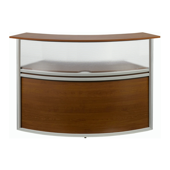
Marque Reception Station
Parts Listing for
Single Section Station
A
B
Transaction Top
Work Surface Top
1 Unit
1 Unit
C
D
Side Wall
Curved Panel
2 Units
1 Unit
E
F
Support Bar
Short Safety Knob
1 Unit
7 Units
G
H
Long Safety Knob
Leveling Glide
2 Units
1 Unit
Assembly Instructions
Please read all instructions before beginning.
NO TOOLS REQUIRED TO ASSEMBLE SINGLE SECTION STATION. Two people are needed for assembly.
• If you purchased models 55290 or 55310 (1 section) follow steps 1-3.
• If you already have an existing Marque Reception Station and are adding sections to it, follow steps 4 - 8.
• If you purchased models 55292 or 55312 (2 sections), 55293 or 55313 (3 sections), 55294 or 55314 (4 sections),
55296 or 55316 (5 sections), follow steps 1A, 6, 7 & 8.
Step 1A:
Step 1B:
Step 2:
Step 3:
NOTE: Please see page 2 to continue assembly of Multi-Section Stations.
1A
1B
D
C
H
C
Assembly Notes:
During assembly, hand tighten screws only. When all screws
are in place, you may then tighten all screws completely.
CAUTION:
1. Do not use this desk as a step ladder.
2. Check for loose screws and tighten them every 6 months.
Insert Leveling Glide ( H ) into base of Curved Panel ( D ) if not already attached. Stand Curved Panel ( D ) up with
Leveling Glide on floor. While one person holds Curved Panel ( D ) , place one Side Wall ( C ) alongside Curved
Panel ( D ) as shown. Slide steel ears on the Curved Panel ( D ) into holes of vertical support beam attached to
Side Wall ( C ) and force downward to lock panel.
Attach other Side Wall ( C ) as explained above.
Place Work Surface Top ( B ) on top of horizontal support beams attached to the Side Walls ( C ) . Attach
Support Bar ( E ) from underneath by placing it diagonally from the front of one Side Wall ( C ) to the back of the
other and secure with two Long Safety Knobs ( G ) . Insert them through the Support Bar ( E ) and the horizontal
support beams of the Side Walls ( C ) then into the bottom of the Work Surface Top ( B ) . Use two Short Safety
Knobs ( F ) to finish attaching Work Surface Top ( B ) by inserting them through remaining holes in the horizontal
support beams of the Side Walls ( C ) and into the bottom of Work Surface Top ( B ) and tighten.
Place Transaction Top ( A ) on support brackets attached to the top of each Side Wall ( C ) and secure using
Short Safety Knobs ( F ) in all holes. Flip up center support tab on inside of Side Wall ( C ) and secure with
Short Safety Knob ( F ). You can now tighten all knobs securely.
2
G
F
F
E
06.29.2016
3
B
F
G
161 Tradition Trail, Holly Springs, NC, 27540
800-520-7471 (voice)
919-303-6389 (voice)
support@ofminc.com
page 1
A
• 919-362-4765 (fax)
• www.ofminc.com
Advertisement

Related Manuals for OFM Marque Series


Summary of Contents for OFM Marque Series
- Page 1 Marque Reception Station page 1 Assembly Instructions Parts Listing for Please read all instructions before beginning. Single Section Station NO TOOLS REQUIRED TO ASSEMBLE SINGLE SECTION STATION. Two people are needed for assembly. • If you purchased models 55290 or 55310 (1 section) follow steps 1-3. •...
- Page 2 Marque Reception Station page 2 Assembly Instructions Parts Listing for Multiple Sections Please read all instructions before beginning. NO TOOLS REQUIRED TO ASSEMBLE Two people are needed for disassembly and reassembly. Transaction Top Work Surface Top 1 Unit Per Section 1 Unit Per Section Note: It is important to build the Reception Station in the place it will be used as it is difficult...
- Page 3 Marque Reception Station page 3 Assembly Instructions, continued Please read all instructions before beginning. NO TOOLS REQUIRED TO ASSEMBLE. Two people are needed for disassembly and reassembly. Note: It is important to build the Reception Station in the place it will be used as it is difficult to move after built.