Table of Contents
Advertisement
Quick Links
ENGINEERING COMPANY INC.
51 Winthrop Road
Chester, Connecticut 06412-0684
Phone: (860) 526-9504
Fax: (860) 526-4078
Internet: www.whelen.com
Sales e-mail: autosale@whelen.com
Canadian Sales e-mail: autocan@whelen.com
Customer Service e-mail: custserv@whelen.com
DANGER!
Sirens produces extremely loud emergency warning tones! Exposure to these
tones without proper and adequate hearing protection, could cause ear damage and/or hearing
loss! The Occupational Safety & Health Administration (www.osha.gov) provides information
necessary to determine safe exposure times in Occupational Noise Exposure Section 1910.95.
Until you have determined the safe exposure times for your specific application, operators and
anyone else in the immediate vicinity should be required to wear an approved hearing protection
device. FAILURE TO FOLLOW THIS RECOMMENDATION COULD CAUSE HEARING LOSS!
Safety First
This document provides all the necessary information to allow your Whelen product to be properly and safely installed.
Before beginning the installation and/or operation of your new product, the installation technician and operator must
read this manual completely. Important information is contained herein that could prevent serious injury or damage.
•
Proper installation of this product requires the installer to have a good understanding of automotive electronics,
systems and procedures.
•
If mounting this product requires drilling holes, the installer MUST be sure that no vehicle components or other
vital parts could be damaged by the drilling process. Check both sides of the mounting surface before drilling
begins. Also de-burr any holes and remove any metal shards or remnants. Install grommets into all wire
passage holes.
•
If this manual states that this product may be mounted with suction cups, magnets, tape or Velcro®, clean the
Mounting surface with a 50/50 mix of isopropyl alcohol and water and dry thoroughly.
•
Do not install this product or route any wires in the deployment area of your air bag. Equipment mounted or
located in the air bag deployment area will damage or reduce the effectiveness of the air bag, or become a
projectile that could cause serious personal injury or death. Refer to your vehicle owner's manual for the air bag
deployment area. The User/Installer assumes full responsibility to determine proper mounting location, based
on providing ultimate safety to all passengers inside the vehicle.
•
For this product to operate at optimum efficiency, a good electrical connection to chassis ground must be
made. The recommended procedure requires the product ground wire to be connected directly to the NEGATIVE
(-) battery post.
•
If this product uses a remote device to activate or control this product, make sure this control is located in an
area that allows both the vehicle and the control to be operated safely in any driving condition. DO NOT
ATTEMPT TO ACTIVATE OR CONTROL THIS DEVICE IN A HAZARDOUS DRIVING SITUATION.
•
It is recommended that these instructions be stored in a safe place and
referred to when performing maintenance and/or reinstallation of this
product.
•
FAILURE
TO
FOLLOW
INSTRUCTIONS COULD RESULT IN DAMAGE TO THE PRODUCT OR
VEHICLE AND/OR SERIOUS INJURY TO YOU AND YOUR PASSENGERS!
For warranty information regarding this product, visit www.whelen.com/warranty
©2006 Whelen Engineering Company Inc.
Form No.14045B (043008)
®
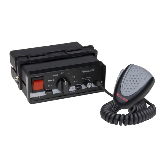
295SL101 (200W - 12V (w/Removable Mic)
THESE
SAFETY
PRECAUTIONS
Page 1
Installation Guide:
Siren Model(s)
295SL100 (200W - 12V)
295SL102 (200W - 24V)
ACTIVATION OF THIS
SIREN MAY DAMAGE
UNPROTECTED EARS!
CAUTION
AND
Loud siren noise can cause
hearing damage and/or loss.
Wear
Refer to OSHA Section 1910.95 prior
to putting ANY siren into service!
Protection!
Advertisement
Table of Contents

Summary of Contents for Whelen Engineering Company 295SL100
- Page 1 ENGINEERING COMPANY INC. Installation Guide: 51 Winthrop Road Chester, Connecticut 06412-0684 Siren Model(s) Phone: (860) 526-9504 295SL100 (200W - 12V) Fax: (860) 526-4078 295SL101 (200W - 12V (w/Removable Mic) Internet: www.whelen.com 295SL102 (200W - 24V) Sales e-mail: autosale@whelen.com Canadian Sales e-mail: autocan@whelen.com Customer Service e-mail: custserv@whelen.com...
- Page 2 Congratulations on selecting the 295SL10 Series Siren! This series offers a unique and distinctive collection of features designed to allow the user to customize the operation of this siren to suit their individual wants or needs. • Power to drive two, 100-Watt •...
- Page 3 Wiring: Power & Ground Wires: RED: Power / BLACK: Ground WARNING! All customer supplied wires that connect to the positive terminal of the battery must be sized to supply at least 125% of the maximum operating current and FUSED at the battery to carry that load. DO NOT USE CIRCUIT BREAKERS WITH THIS PRODUCT! Splice the 2 RED (Power) wires together, then extend this single RED wire toward the vehicle battery.
- Page 4 Connecting to a Remote Control Head: OPERATING THE CONTROLS: (Optional) POWER SWITCH This unit may be connected to an existing control head, This switch has two positions: Down (Off) and Up such as the Whelen PCDS-9 or equivalent. This is an (On).
- Page 5 Rotary Switch Operations This section will outline the operation of the siren in the factory wired to the HORN RING input). The first tap produces a Wail default configuration. Refer to the Scan-Lock™ section on the tone (a steady rise and fall tone). A second tap produces a Yelp following page for information and procedures on how to tone (a fast rise and fall tone).
- Page 6 Scan-Lock™ Programing Procedures With Scan-Lock the tonal operation of the siren can be manual: Put the rotary switch in the HF position. Using the MAN customized to fit the users needs. A momentary switch, accessed button on the front panel on the siren, advance to the tone that through a small hole on the back of the siren, is used to change you wish to change.
- Page 7 Wire Gauge Calculation Chart Wire Gauge (AWG) 24.5 19.5 INS. 20.5 32.5 82.5 INS. INS. 15.5 24.5 98.5 INS. INS. 12.5 19.5 49.5 INS. INS. INS. 10.5 16.5 41.5 INS. INS. INS. 22.5 35.5 56.5 89.5 INS. INS. INS. 12.5 19.5 49.5 78.5...