Advertisement
Quick Links
Thank you for choosing Minoura 971-3.
Read this instructions carefully to understand well how this stand is constructed before starting assembling.
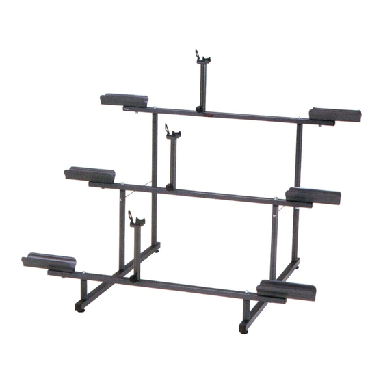
Completed image and dimensions of 971-3
(in the settings the bikes facing rightward)
IMPORTANT NOTES
!
• For standard 2-wheel bike only. No recumbent, tandem and any other type of bikes.
• For 24-inch wheel or larger only. Any bike with smaller wheel such as BMX or juvenile bike, and a special bike
with too low bottom bracket height or carbon monocoque frame may not fit to this stand.
• In the case of electric bike, the weight is limited under 30 kgs each.
• The bike is supported at just 3 points; front tire, rear tire and the bottom bracket. Adjust the BB Support height
precisely in each case to expect maximum stability.
• The bike direction is fixed as per the Stair Frame direction. Wrong direction cannot mount the bike properly.
• Do not step on this stand. The stand body is not so durable to support your weight.
• Setup this stand on horizontal and level floor, especially when installing the optional Caster Kit.
• When moving this stand, get off all bikes from the stand before action.
• Check regularly if each bolt and nut are firmly tightened.
Contact
Bicycle Display Stand
MINOURA JAPAN
134-1 Shimomiya, Godo, Anpachi, Gifu 503-2312 Japan
Fax: +81-584-27-7505
Mail: minoura@minoura.jp
Web: www.minoura.jp
Made in Japan
- 1 -
971-3
instructions manual
(ver.2.4 2019/4)
Advertisement

Summary of Contents for MINOURA 971-3
- Page 1 Bicycle Display Stand instructions manual (ver.2.4 2019/4) Thank you for choosing Minoura 971-3. Read this instructions carefully to understand well how this stand is constructed before starting assembling. Completed image and dimensions of 971-3 (in the settings the bikes facing rightward) IMPORTANT NOTES •...
-
Page 2: Required Tools
H ow To As s e m b l e 9 7 1 - 3 Required Tools: 1 x Phillips Screwdriver (#2), 2 x 13mm Socsket Wrench First of all, check all small parts are correctly prepared. Connect both Side Frames with three (3) Stair Frames. Parts List On the 1st level Stair Frame, you use longer M8x60 bolt. - Page 3 Install a pair of Tire Cradles on each Stair Frame. Each Tire Cradle is position adjustable in 5 points in order to fit Tire Cradle various sizes of bike wheelbase. To expect maximum stability of bikes, choose the best position each by each.
- Page 4 O pt iona l It e m s By replacing the Foot Adjuster to a caster wheel, you can If you cannot hold the bike on 971-3 stable due to the move 971-3 to anywhere while mounting bikes on it.