Advertisement
Quick Links
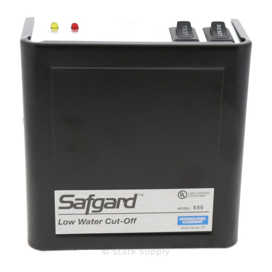
Low Water Cut-Offs
550 / 650 / 750 Series
120 VAC Operating Voltage
WARNING: To prevent electrical shock or equipment damage, power must be off during installation or servicing of the control. To prevent
serious burns, the boiler should be thoroughly cooled before installing or servicing control. Only qualified personnel may install or service
the control in accordance with local codes and ordinances. Read instructions completely before proceeding.
1. Where To Install
HOT WATER BOILER
INSTALLATIONS
B
C
A
MINIMUM
WATER LEVEL
HOT WATER BOILERS: Probe must be installed at or
above the minimum safe water level established by the
boiler manufacturer. The probe may be installed directly
in the boiler (A) if a suitable tapping is available, in the
riser (B), in the header horizontally (C), or in the header
vertically (D). IMPORTANT: To assure proper drainage,
pipe diameter should be no less than 1" on installations
in vertical piping and no less than 1
1
horizontal piping.
2. Tee Options
STANDARD
FABRICATED TEE
REDUCING TEE
(SV Models Only)
TEE MOUNTING: If a field fabricated tee is used, make sure that the tee drains thor-
oughly when the water level falls below it, and that it conforms to the spacing require-
ments described in Step 3. Models equipped with the shorter EL1214-SV probe can be
installed in most standard reducing tees. Safgard cast iron tees are also available to
accommodate all probe models (See page 4).
4. Control Mounting
Loosen the two control box cover bind-
ing head screws and remove the cover.
D
TYPICAL STEAM BOILER
INSTALLATIONS
SECONDARY
LWCO
HOT WATER
BOILER
A
STEAM BOILERS (Secondary) : Control must be installed in a suitable tapping provided in
the boiler(A), or in an equalizing line(B). The control should be located below the level of the
primary low water cut-off but above the lowest permissable water line as specified by the
boiler manufacturer.
Note: For installations in equalizing lines, Hydrolevel recommends the use of Safgard Tees
(see step 2).
⁄
" on installations in
4
FOEM-TEE
1214C-2 TEE
(160psi)
(250psi)
Slide keyhole slots over probe mounting
screws and tighten screws (with either a
1/4" hex head driver or flat screwdriver.
Automatically shuts off burner in a low water condition to prevent
boiler damage.
Low maintenance. No moving parts to wear stick or hang up, as in
float devices.
Test button (550 & 650 Series) allows the burner circuit and
control to be tested without lowering the water level.
Manual reset feature (550 & 750 Series) will not lock out in power
failures.
LOW WATER
CUT-OFF PUMP
CONTROLLER
3. Probe Installation
Apply pipe sealing compound to
threads before installing probe.
Teflon tape is not recommended.
Check to insure 1/4" clearance from
probe to any surface or tee.
Connect the ring terminal wire lead to the probe terminal
stud and secure with the lock washer and wing nut provided.
ith the power removed, proceed with installation and
wiring according to Method A or B described on next page.
LOW WATER
CUT-OFF PUMP
CONTROLLER
SECONDARY
LWCO
B
CAUTION: The probe tip
must extend fully into the
boiler or pipe run. If the
probe is recessed, sedi-
ment can build up and
prevent the low water cut-
off from operating.
Advertisement

Summary of Contents for safgard 550 Series
- Page 1 Step 3. Models equipped with the shorter EL1214-SV probe can be Check to insure 1/4" clearance from probe is recessed, sedi- installed in most standard reducing tees. Safgard cast iron tees are also available to probe to any surface or tee. ment can build up and accommodate all probe models (See page 4).
- Page 2 WIRING METHOD A: SAME POWER SOURCE FOR CONTROL AND BURNER CIRCUIT. Connect the hot lead of the input volt- age (120 VAC, 60 HZ) to terminal 1. Connect the neutral lead to terminal 2. 120 VAC, 60 HZ must be supplied to terminals 1 and 2 for internal operation of the control.
-
Page 3: Operating Instructions
WIRING METHOD C: SECONDARY CUT-OFF When a Safgard 550/750 is used as a secondary low water cut-off on a steam boiler, the following wiring instructions should be used. The diagram below depicts the 550/750 as a secondary control wired in series with a Safgard Model 450/CG450. Consult boiler manufacturer’s instructions for the location of a tapping recommended for a secondary low water cut-off. -
Page 4: Specifications
FITTINGS Controls equipped with the EL1214-SV Probe can be mounted in standard reducing tees (supplied by others). Safgard manifolds, listed below, can be used with all probe models. MODEL SIZE FOEM-1 1 1/2" x 1 1/2" x 3/4"NPT FOEM-2 1" x 1" x 3/4"NPT FOEM-3 1 1/4"...