Advertisement
Quick Links
Installation / Installation / Instalación
Mounting Plate
A
Plate décorative
placa de pared decorativa
Electrical Box
B
12.0
Boîte électrique
31.8
Caja elétrica
Machine screw
63.5
C
Vis mécanique
Tornillo
fantech
fantech
Not included
D
Non inclus
No se incluye
Wiring Diagram / Branchement électrique / Cableado
A
B
VT20A
VT20M
Contacts:
United States / États-Unis / Estades Unidos Americanos
10048 Industrial Blvd., Lenexa, KS, 66215
Tel.: 800.747.1762 • Fax: 800.487.9915
fantech
30.0
15.0
R1.0
B
4.0
A
20.0
fantech
4.0
C
D
Auxiliary control
Red
A
F
Contrôle auxiliaire
Rouge
Control auxiliar
Rojo
Main control
Neutral
B
G
Contrôle principal
Neutre
Control principal
Neutral
Fan
Line
C
H
Ventilateur
Ligne
Ventilador
Línea
G
White
Load
D
I
Blanc
Charge
H
H
Blanco
Carga
Black
E
Noir
Negro
Canada / Canada / Canadá
50 Kanalflakt Way, Bouctouche, NB, E4S 3M5
Tel.: 800.565.3548 • Fax: 877.747.8116
VT20M & VT20A
Intermittent Fan Control
WARNING: Ensure that power
is switched off at service
panel before commencing
installation.
WARNING: Main Control Unit
and Auxiliary Control Unit
must not be installed where
they can be reached from a
tub or a shower. Unit must
D
be installed on GFCI circuit if
located in bathroom.
Electrical wiring must be
done by qualified person(s) in
accordance with all applicable
codes and standards
NORMAL OPERATION
Main Control unit (VT20M) features both a timer and
speed control that will activate an exhaust fan at a
certain speed for a selected period of time each hour.
To select fan speed, adjust lover slide control to desired
speed. To select fan on-time, ajust upper slide control
to time desired (5 minute intervals). For example, if the
fan-on time (upper slide adjuster) is set at one quarter
from the bottom, the fan will run for 15 minutes every
hour at the preset speed (lower slide adjuster).
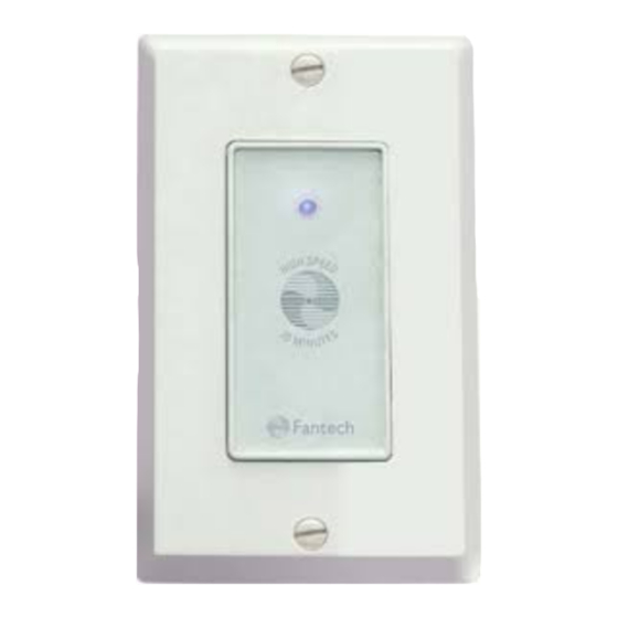
For temporary full speed onperation, press the button
on the front of the control (main or auxiliray). The fan
will run at full speed for 20 minutes and the resume
its normal preset cycle. Full speed is indicated by a
blue light illuminated on the front of the control panel.
To return to the normal cycle before 20 minutes had
elapsed, press and hold the button for five seconds.
AUXILIRAY CONTROL UNIT
Up to three auxiliray control units can be installed in
addition to one main control unit. Install in standard
wall box. Two insulated ROMEX type wires are required
to connect main control unit to auxiliary control units.
Connect the positive screw terminal on the main control
unit to the positive screw terminal on the auxiliary
control unit. Connect the negative terminals the same
way.
DESCRIPTION
The Fantech intermittent Fan Control is designed to be used with
Fantech FG, FR, FQ and PB fans only to meet whole-house ventilation
needs as prescribed by independent residential ventilation authorities
such as HVI and ASHRAE.
The model VT20M controller enables the fan to run at a preset speed
for a preset portion of each hour, 24 hours a day everyday.
The high speed override button enables the fan to run at full speed for
20 minutes wheh needed, for example to vent steam from a bathroom.
Where a single exhaust fan is ducted to draw air from multiple
locations, up to three auxiliary fan controls, model VT20A, may be used
with the main controller, model VT20M.
The auxiliary controls may be installed in secondary bathrooms etc.,
where high speed overrides is required.
SPECIFICATIONS
For control of 120V AC exhaust fans up to 2.5A.
Use only with 120V AC single phase electrical supply.
MAIN CONTROL UNIT
• Install in standard wall box prewired with LINE and
NEUTRAL.
• Using twist wire connectors, connect NEUTRAL to
both the WHITE wire on the main control unit and to
the NEUTRAL terminal on the remote fan.
• Connect LINE to the BLACK wire on the main control
unit.
• Connect the RED wire on the main control unit to the
LINE terminal on the remote fan. See wiring diagram
for more details.
• Screw the main control unit into the wall box so that it
is flush with the wall.
• Restore power at the service panel and push high
speed button to verify power to the remote fan.
• Adjust time and speed adjuster to deisred levels and
install the decorative wall plate.
The wall plate must be removed to make
adjustmnents to time and speed.
Item #: 407392
Rev Date: 052014
fantech
Advertisement

Related Manuals for Fantech VT20M

Summary of Contents for Fantech VT20M
- Page 1 Not included WARNING: Main Control Unit The model VT20M controller enables the fan to run at a preset speed Non inclus and Auxiliary Control Unit for a preset portion of each hour, 24 hours a day everyday. No se incluye...
- Page 2 électrique est Fantech a été conçu d’après les besoins «Whole-House» prescrites par des con los ventiladores FG, FR, FQ y PB de Fantech fin de satisface la de eletricidad esté apagada en el débranché au panneau de personnes autorisées indépendantes de la ventilation résidentielle comme...