Advertisement
Quick Links
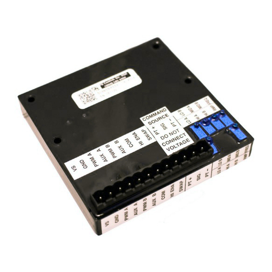
OPERATIONS MANUAL
Features
♦ Independent Low Current Adjustment
♦ Independent Mid Current Adjustment
♦ Independent Hi Current Adjustment
♦ Adjustable RAMP
♦ Adjustable PWM Frequency
♦ Dual Output Range (Mid/Hi)
♦ Swap Feature
♦ RAMP Duration Between MID and HI Ranges
♦ Current Sourcing w/Feedback Outputs
♦ 2.5 Amp FET On/Off Outputs
♦ Over-Signal Protection
♦ Short Circuit Protection
♦ Reverse Polarity Protection
♦ Voltage Supply Transient Protection
♦ EMI and RFI Resistant
Description
The Model 504 series of valve drive boards are an electronic interface between a command source
(potentiometer, joystick, footpedal, etc.) and an electro-hydraulic valve or pump. The board receives
analog signals from the command source, and provides Pulse Width Modulated Output (PWM) to drive
most electrically modulated valves and pumps available today. The board also provides On/Off Outputs
and other features to smoothly stroke a valve or pump with greater control and flexibility over
conventional hydraulic components. The 504 family of valve drive boards are designed for use on mobile
equipment where extreme environments (both weather and electrical) are encountered. The boards also
offer features used in many industrial applications. The 504 board can be mounted directly to P-Q single
axis joysticks or can be remotely mounted up to 100 feet from the command source.
Output from the proportional channels is Pulse Width Modulated (PWM) with current monitoring. The
Model 504 boards can be configured to drive single coil, dual coil, single coil (flow control) grounded
coil valves, or single coil floating valves. The proportional current output will remain fixed within 2%
during supply voltage swings, and coil resistance changes, (which occurs as the valve coil temperature
rises). Light emitting diodes (LED's) are lit whenever the command signal exceeds the board's deadband
and the board begins to output. Should any of the outputs (digital or proportional) be shorted, the outputs
will automatically shut down.
Property of P-Q Controls, Inc.
P-Q Controls, Inc.
Phone (860) 583-6994
Fax
(860) 583-6011
95 Dolphin Road
Bristol, CT, 06010
MODEL 504 / 514 / 524 / 534
504Manual.Doc
Doc. No:
F
Date:
Rev:
CAM
Author:
Page:
504
www.p-qcontrols.com
10/24/13
1 of 5
Advertisement

Summary of Contents for P-Q Controls 504 Series
- Page 1 ♦ EMI and RFI Resistant Description The Model 504 series of valve drive boards are an electronic interface between a command source (potentiometer, joystick, footpedal, etc.) and an electro-hydraulic valve or pump. The board receives analog signals from the command source, and provides Pulse Width Modulated Output (PWM) to drive most electrically modulated valves and pumps available today.
- Page 2 OPERATIONS MANUAL MODEL 504 / 514 / 524 /534 Page 2 of 5 In addition to the proportional outputs, On/Off (digital) outputs are available to energize dump valves, blocking valves, brakes, buzzers, etc. These solid state auxiliary outputs utilize field effect transistors (FET’s) to provide continuous loads up to 2.5 Amps.
-
Page 3: Operational Considerations
OPERATIONS MANUAL MODEL 504 / 514 / 524 /534 Page 3 of 5 Operational Considerations Voltage Supply: The board is capable of functioning properly when supplied with a DC voltage ranging from 10-30 volts. To ensure proper operation, the DC ripple should be limited to less than 15% of the supply voltage. - Page 4 OPERATIONS MANUAL MODEL 504 / 514 / 524 /534 Page 4 of 5 PT- and PT+ : The PT+ and PT- terminals provide 5VDC or 6VDC for the command source (check your specific part number). These terminals are intended to be connected to a 500 Ohm potentiometer with 180Ω...
- Page 5 OPERATIONS MANUAL MODEL 504 / 514 / 524 /534 Page 5 of 5 504Manual.Doc...