Advertisement
Quick Links
3
Optional
Typical Wiring Diagram For Heat/cool, 4 Wire, Single Transformer Systems
Optional
4
Typical Wiring Diagram For Heat/cool, 5 Wire, Two Transformer Systems
Optional
5
Typical Wiring Diagram For Heat Pump With Reversing Valve Energized In Cool
6
Optional
Typical Wiring Diagram For Heat Pump With Reversing Valve Energized In Heat
2012
YSP Inc.
©
220V
220V
220V
220V
220V
BRT36011
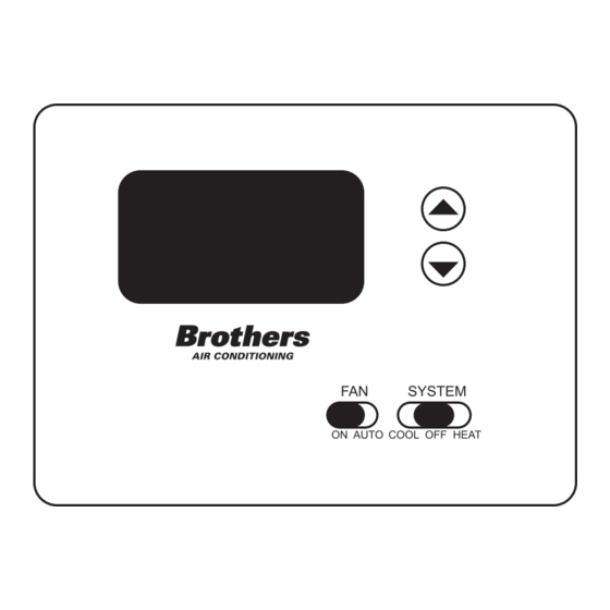
T-360 and T-360HP
Non-Programmable Thermostat
Installation Instructions
Advertisement

Summary of Contents for Brother T-360HP
- Page 1 Typical Wiring Diagram For Heat/cool, 5 Wire, Two Transformer Systems Optional 220V Typical Wiring Diagram For Heat Pump With Reversing Valve Energized In Cool Optional T-360 and T-360HP 220V Non-Programmable Thermostat Typical Wiring Diagram For Heat Pump With Reversing Valve Energized In Heat 2012 YSP Inc.
- Page 2 Battery Location To Prevent electrical shock and/or equipment damage, disconnect electrical power to the system at the main fuse The thermostat can function on 2 x “AA” alkaline or circuit breaker until installation is complete. batteries as an alternative source of power. change is displayed, the batteries are low and should be replaced.